An OFF delay timer is a commonly used timer instruction in a Programmable Logic Controller (PLC). It keeps an output ON for a preset period after the input signal turns OFF. This function is useful in applications where equipment must continue operating for a specific time after the main control signal has been removed.
For example, an industrial cooling fan may need to continue running for 10 minutes after a motor stops. An OFF delay timer can control this operation automatically. It is also used in ventilation systems, pumps, lighting circuits, and industrial process control.
This article explains the OFF delay timer, its working principle, timer parameters, and an example of its implementation using Allen-Bradley PLC ladder logic.
What Is an OFF Delay Timer?
An OFF delay timer is a PLC timer instruction that delays the switching OFF of an output after its controlling input becomes FALSE (OFF).
When the input signal becomes TRUE (ON), the timer output is activated immediately. When the input signal changes to FALSE, the timer starts counting. The output remains ON during the preset time interval and switches OFF when the accumulated time reaches the preset value.
The main purpose of an OFF delay timer is to maintain an output for a specified duration after the input signal has been removed.
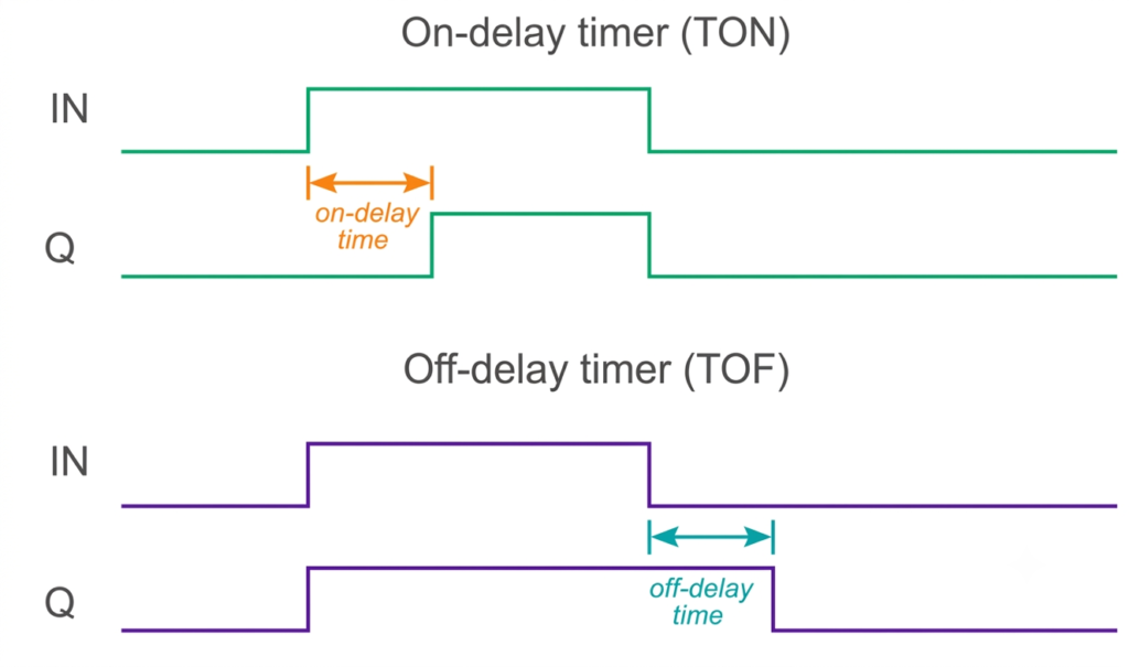
Example: Consider a cooling fan connected to an electric motor. The fan operates whenever the motor is running. When the motor stops, the fan continues running for another 10 minutes to remove the remaining heat. After 10 minutes, the fan switches OFF automatically.
OFF Delay Timer Parameters in Allen-Bradley PLC
In Allen-Bradley PLCs, timer instructions use several parameters to define and monitor the timing operation. In the traditional RSLogix 500 timer structure, a timer such as T4:0 contains the following elements:
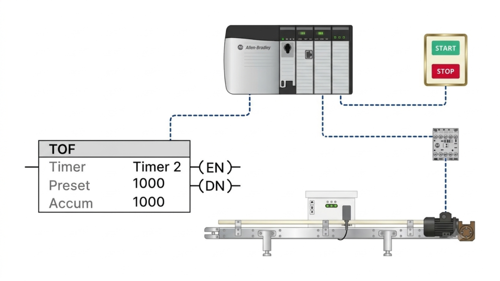
Timer Address (T4:0): Identifies the timer being used in the PLC program. For example, T4:0, T4:1, and T4:2 represent different timer elements in the traditional Allen-Bradley SLC 500 and MicroLogix timer file structure.
Time Base: Defines the time unit used by the timer. Depending on the PLC family and instruction, the time base may be expressed in seconds, milliseconds, or another supported interval.
Preset (PRE): Specifies the total time the timer must count before completing its timing operation. For a 10-minute delay, the preset must be configured according to the selected timer time base.
Accumulator (ACC): Displays the elapsed time accumulated by the timer during its timing operation. The value increases until it reaches the preset value.
The timer also uses status bits to indicate its operating condition.
| Status Bit | Description |
| EN (Enable) | Indicates the enable status of the timer instruction. |
| TT (Timer Timing) | Indicates that the timer is currently counting. |
| DN (Timer Done) | Indicates that the timer has completed its timing operation or is in its done state. |
The exact status-bit behaviour depends on the PLC family and timer instruction. Always refer to the relevant Allen-Bradley programming manual when developing or troubleshooting a program.
Working Principle of an OFF Delay Timer
The OFF delay timer operates in two main conditions: when the input signal is ON and when the input signal changes to OFF.
When the input is ON: The timer’s done status is activated, and the controlled output turns ON immediately. The timer does not introduce a delay when the input becomes active.
When the input changes to OFF: The timer starts its timing sequence. The accumulated value increases while the output remains ON. When the accumulated time reaches the preset value, the timer completes the delay and its done status turns OFF. Consequently, the controlled output switches OFF.
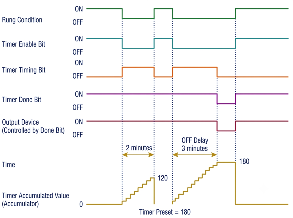
For example, assume the OFF delay timer is configured with a preset of 10 minutes.
- The motor starts, and the cooling fan switches ON.
- The motor continues running, so the fan remains ON.
- The motor stops, and the OFF delay timer begins counting.
- The cooling fan continues running during the 10-minute delay.
- After 10 minutes, the timer completes its operation and the fan switches OFF.
This arrangement prevents the fan from stopping immediately when the motor is switched OFF.
OFF Delay Timer Using Allen-Bradley PLC Ladder Logic
An OFF delay timer can be implemented in Allen-Bradley PLCs using the TOF (Timer Off Delay) instruction.
The following example demonstrates how to operate a cooling fan for 10 minutes after an electric motor stops.
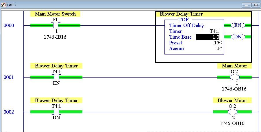
Program Description
Consider a system with a motor start/stop command and an auxiliary cooling fan. The fan must operate whenever the motor is running and remain ON for 10 minutes after the motor stops.
The TOF instruction is configured with a preset value equivalent to 10 minutes.
Rung 0000: Motor Start/Stop Control
The start and stop control circuit determines whether the motor is operating. When the motor is running, the input condition connected to the OFF delay timer remains TRUE.
When the motor stops, this input condition changes to FALSE, initiating the OFF delay operation.
Rung 0001: OFF Delay Timer Instruction
The TOF instruction monitors the motor-running condition.
When the motor-running signal is TRUE, the timer done bit remains set, allowing the cooling fan output to operate immediately.
When the motor-running signal becomes FALSE, the timer begins accumulating time. The timer timing bit indicates that the OFF delay period is in progress.
Rung 0002: Cooling Fan Output
The cooling fan is controlled through the timer’s done bit.
As long as the timer done bit remains TRUE, the cooling fan stays ON. This includes the period when the motor is running and the additional 10-minute interval after the motor stops.
When the timer reaches its preset value, the done bit changes to FALSE, switching OFF the cooling fan.
OFF Delay Timer Example: Cooling Fan Operation
Assume the following operating conditions:
| Parameter | Value |
| Motor status | ON/OFF |
| Timer instruction | TOF |
| Timer preset | 10 minutes |
| Cooling fan operation | During motor operation and after shutdown |
| Delayed OFF time | 10 minutes |
The operation can be understood through the following sequence:
| Operating Condition | Motor | Timer Status | Cooling Fan |
| Normal operation | ON | Done | ON |
| Motor switched OFF | OFF | Timing | ON |
| 5 minutes elapsed | OFF | Timing | ON |
| 10 minutes elapsed | OFF | Timing complete | OFF |
The timer automatically switches OFF the cooling fan after the preset delay has elapsed.
Applications of OFF Delay Timers
OFF delay timers are used in industrial automation wherever an output must remain active for a specified time after its input signal turns OFF.
Common applications include:
- Motor cooling fans: Keep cooling fans running after a motor stops to remove residual heat.
- Industrial ventilation: Continue operating exhaust fans after a machine or process has stopped.
- Lighting control: Keep lights ON for a preset period after a control signal is removed.
- Pump control: Maintain pump operation for a defined period after a process command changes, where the process design permits it.
- Conveyor systems: Keep selected auxiliary equipment running briefly after the main conveyor stops.
- Air-conditioning systems: Continue operating selected ventilation components after the main cooling command is removed.
OFF Delay Timer vs ON Delay Timer
ON delay and OFF delay timers are two commonly used PLC timer instructions. Their main difference is the point at which they introduce a time delay.
| Basis | ON Delay Timer (TON) | OFF Delay Timer (TOF) |
|---|---|---|
| Function | Delays switching ON of an output | Delays switching OFF of an output |
| Input becomes ON | Starts timing | Output activates immediately |
| Input becomes OFF | Resets timing according to instruction behaviour | Starts the OFF delay period |
| Output activation | After the preset time | Immediately when input becomes ON |
| Output deactivation | When input becomes OFF | After the preset delay |
| Common application | Delayed motor starting | Motor cooling fan after shutdown |
Important Points When Using an OFF Delay Timer
Before implementing an OFF delay timer in a PLC program, consider the following points:
- Select the correct timer instruction for the PLC platform.
- Configure the preset value and time base correctly.
- Check the timer’s EN, TT, and DN status bits during testing.
- Verify the output behaviour when the input signal changes state.
- Consider what happens if the PLC loses power or enters a fault condition.
- Use an appropriate motor starter, contactor, or interposing relay when required to operate external loads.
Note: Allen-Bradley PLC families may use different timer data structures and programming environments. The traditional T4:0 addressing convention applies to certain RSLogix 500 platforms. Logix 5000 controllers use a different timer tag structure. The program should therefore be adapted to the specific controller and software version.
Conclusion
An OFF delay timer is useful in PLC automation when an output must remain ON for a specified time after its input signal turns OFF. The Allen-Bradley TOF instruction performs this function by starting the timing sequence when the rung condition becomes FALSE. It is commonly used in motor cooling, ventilation, lighting, and other industrial control applications where delayed switching OFF is required.
Read Next: