In process industries such as oil & gas, pharmaceuticals, food processing, chemical manufacturing, and power generation, control valves play a pivotal role in regulating the flow of fluids. However, for a control valve to function with high accuracy, it must open to the correct position in response to the control signal. This is where understanding the types of valve positioners becomes essential, because the right positioner ensures precise valve movement and consistent process control.
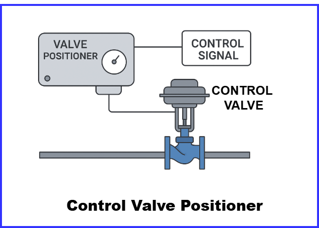
A valve positioner is a device installed on a control valve to ensure the valve stem moves to the exact position dictated by the control signal. Without a positioner, friction, mechanical wear, and pressure variations can cause the valve to deviate from its desired position, affecting process accuracy and system efficiency.
This article explains what a valve positioner is, why it is needed, and provides a detailed explanation of the types of valve positioners, along with their working principles, applications, advantages, and disadvantages.
What is a Valve Positioner?
A valve positioner is a precision control device installed on a control valve actuator to ensure the valve opens to the exact position required by the control signal from the controller (such as a PLC or DCS). In many real-world applications, mechanical friction, varying process pressures, or actuator limitations can prevent a valve from reaching the correct position. This is where the positioner becomes essential.
The positioner continuously compares two values:
- The input control signal (e.g., 3–15 psi or 4–20 mA)
- The actual valve stem position, measured through a feedback mechanism
If there is any difference between the desired position and the actual position—called position error—the positioner automatically adjusts the air pressure to the actuator until the valve reaches the correct travel. This closed-loop action ensures accurate, stable, and repeatable valve movement, even in demanding process conditions.
In short, a valve positioner improves control accuracy, response speed, and reliability, making it a critical component in modern industrial automation systems.
Why Are Valve Positioners Needed?
Valve positioners play a critical role in ensuring that control valves move to the exact position required by the control signal. Without a positioner, the actuator may not respond accurately due to friction, mechanical wear, or varying process pressures. This can cause instability, poor control performance, and inefficiencies in the process. Positioners compensate for these issues by constantly monitoring the valve stem position and adjusting air pressure to maintain the correct travel.
Valve positioners are especially needed in the following situations:
- When precise valve control is required:
In processes that require tight control of flow, pressure, temperature, or level, even small deviations can affect product quality. Positioners ensure accurate and repeatable valve positioning for high-performance control loops. - When actuator force is insufficient to overcome friction or process load:
Mechanical friction in valve packing, stems, and linkages, or high differential pressure across the valve, can prevent the actuator from reaching the commanded position. Positioners boost and modulate air pressure to overcome these forces. - When rapid response to control signals is needed:
In dynamic systems where setpoints change frequently, a positioner enables faster valve movement and prevents lag or oscillation, improving control loop stability. - When supply air pressure fluctuates:
Variations in instrument air can lead to inconsistent actuator performance. Positioners regulate and stabilize the air pressure to maintain accurate valve positioning. - In critical process applications requiring high accuracy and reliability:
Industries such as pharmaceuticals, chemical manufacturing, oil & gas, and power plants rely on positioners to ensure safety, efficiency, and compliance with quality standards.
Types of Valve Positioners
Valve positioners can be classified based on their operating principles and the type of signal they receive:
| Classification Basis | Types |
| Based on Control Signal | Pneumatic, Electro-Pneumatic, Digital/Smart |
| Based on Action | Direct Acting, Reverse Acting |
| Based on Feedback Mechanism | Single Acting, Double Acting |
The three main types of valve positioners are:
- Pneumatic Valve Positioners
- Electro-Pneumatic (I/P) Valve Positioners
- Digital/Smart Valve Positioners
Let’s discuss each in detail.
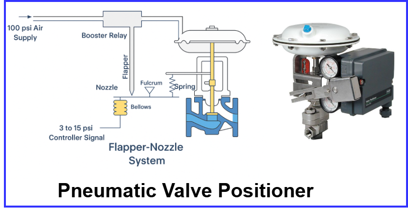
1. Pneumatic Valve Positioners
A pneumatic valve positioner receives a pneumatic (air pressure) signal, typically 3–15 psi, from a controller and adjusts the valve actuator accordingly. It uses a system of nozzles, flappers, bellows, and diaphragms to sense signal pressure and valve stem movement.
Working Principle
- The controller sends a pneumatic signal to the positioner.
- The positioner compares this signal with the feedback from the valve stem.
- If there is any difference (error), the positioner adjusts the air supply to the actuator.
- This changes the actuator pressure, moving the valve to the correct position.
Applications
- Power plants
- Oil & gas refineries
- Chemical processing units
- Remote or hazardous areas where electricity is not preferred
Advantages
- Works without electricity (safe for explosive environments)
- Simple design and reliable operation
- Low maintenance
Disadvantages
- Lower accuracy compared to smart positioners
- Susceptible to air quality issues (water/oil in air lines)
- Slower response time
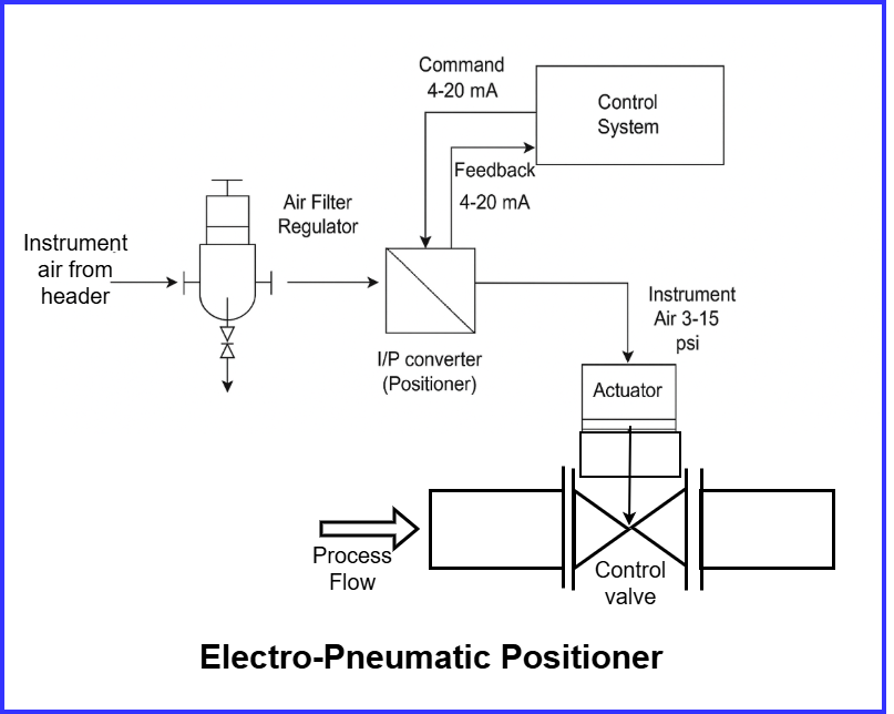
2. Electro-Pneumatic (I/P) Valve Positioners
Electro-pneumatic valve positioners, also known as I/P or E/P positioners, accept an electrical signal (usually 4–20 mA) and convert it to a pneumatic output to control the actuator.
Here, I/P Transducer converts current (I) to pressure (P).
Working Principle
- A controller sends a 4–20 mA electrical control signal.
- The I/P converter transforms this signal into a pneumatic pressure (3–15 psi).
- Positioner compares this pressure with valve position feedback.
- It regulates air supply to ensure the valve moves to the desired position.
Applications
- Sites with electronic control systems (DCS/PLC)
- Automation and SCADA-based process plants
- Systems requiring remote control and monitoring
Advantages
- Higher accuracy than pneumatic positioners
- Compatible with modern electronic control systems
- Faster response time
Disadvantages
- Requires electrical power, not suitable for all hazardous zones unless certified
- Sensitive to vibration and electrical noise
- Higher maintenance compared to pneumatic types
3. Digital / Smart Valve Positioners
Digital or smart valve positioners are the most advanced type. They use microprocessors and digital communication protocols such as HART, Fieldbus, or Profibus. They provide high accuracy, self-diagnostics, and remote calibration.
Working Principle
- The controller sends a digital signal (4–20 mA + HART, Fieldbus etc.).
- The smart positioner uses a microcontroller to interpret the signal.
- Built-in sensors provide continuous feedback on valve position.
- The positioner adjusts air supply automatically for precise positioning.
- Diagnostic features monitor valve health and performance.
Applications
- Modern automated industries
- Batch processing plants
- Pharmaceutical and food industries requiring precision
- Systems requiring predictive maintenance
Advantages
- Very high accuracy and repeatability
- Remote calibration and configuration
- Built-in diagnostics improve reliability
- Reduces downtime and maintenance costs
Disadvantages
- Higher cost
- Requires skilled personnel for configuration
- Requires stable and clean power supply
Comparison Table: Types of Valve Positioners
| Feature | Pneumatic | Electro-Pneumatic | Digital / Smart |
| Signal Type | 3–15 psi | 4–20 mA + Air | Digital / HART / Fieldbus |
| Accuracy | Medium | High | Very High |
| Diagnostics | No | Limited | Extensive |
| Cost | Low | Medium | High |
| Speed of Response | Medium | Fast | Very Fast |
| Ideal Use | Hazardous or remote areas | Industrial automation | Modern smart plants |
Smart Positioners and Digital Diagnostics: Enhancing Reliability and Maintenance Insight
Modern smart valve positioners offer advanced diagnostic capabilities that significantly improve plant reliability and maintenance planning. Instead of waiting for a valve to fail or degrade performance, digital positioners continuously monitor valve behavior, detect mechanical issues early, and provide actionable data for maintenance teams.
One of the most valuable diagnostic features is Partial Stroke Testing (PST). This test is especially important for emergency shutdown (ESD) valves, which often remain in one position for long periods. In a PST, the valve is moved only a small amount (typically 10–20% of its full travel) without affecting the ongoing process.
This small movement confirms that the valve is operational and not stuck due to corrosion, friction buildup, or seal damage. This helps ensure the valve will respond correctly during an emergency event.
Another key diagnostic tool is Valve Signature Analysis. A valve signature is a plotted curve showing actuator pressure versus valve travel. It effectively creates a performance “fingerprint” of the valve. By analyzing this signature, technicians can detect issues such as:
- Excessive friction
- Stiction (stick-slip motion)
- Actuator spring wear
- Seal degradation
- Seat damage
Comparing valve signatures over time allows maintenance teams to predict failures before they occur, enabling proactive repair scheduling rather than emergency shutdowns.
A Special Application: Split-Range Control
Split-range control is a technique where a single controller output signal operates two or more control valves, and each valve responds to a different portion of that signal. This method is useful when:
- One valve alone cannot cover the full operating range
- Fine control is needed at low flow and high-capacity control at higher flow
- A process must switch smoothly between two different control actions
In this setup, the valve positioners are calibrated so each valve responds only within its assigned signal range. For example:
- 0–50% controller output → Small valve opens for precise, low-flow control
- 51–100% controller output → Large valve opens for high-flow capacity
This prevents both valves from moving at the same time and ensures smooth, stable regulation.
Key Points About Split-Range Control:
- It uses one controller to manage multiple valves.
- Positioners are essential, as they allow different signal ranges for each valve.
- It enhances efficiency by matching valve size and response to actual process demand.
- It is commonly used in:
- Heating/Cooling systems (steam valve vs. cooling water valve)
- Flow control loops (small “trim” valve + large main valve)
- Pressure control systems (low-flow and high-flow valves working together)
By correctly configuring the signal ranges in the positioners, split-range control achieves accurate, stable, and efficient system performance over a wide operating range.
Selection Criteria for Valve Positioners
Choosing the appropriate positioner is essential for accurate valve control, stable operation, and reliable system performance. The right selection improves efficiency, reduces wear, minimizes downtime, and ensures the process responds as intended. Below are the key factors to consider:
- Type of Control Signal
Determine whether the system uses Pneumatic (3–15 psi), Analog/Electronic (4–20 mA), or Digital communication (HART®, FOUNDATION™ Fieldbus, PROFIBUS®). The positioner must be compatible with the existing control signal and communication method. - Actuator Type
Match the positioner to actuator characteristics:
• Single-acting for spring-return fail-safe functions
• Double-acting for stronger, faster control
• Linear actuators for globe/gate/diaphragm valves
• Rotary actuators for ball, butterfly, or plug valves - Hazardous Area Classification
If flammable gases or vapors are present, select intrinsically safe or explosion-proof positioners. Always confirm certification before installation. - Required Accuracy and Control Performance
Critical, high-precision processes benefit from digital/smart positioners; electro-pneumatic suits general control; pneumatic works for basic loops. - Diagnostic and Monitoring Needs
Smart positioners enable travel feedback, cycle counting, friction monitoring, and predictive maintenance insights. Traditional models only position the valve. - Environmental and Operating Conditions
Consider humidity, corrosion, temperature, vibration, and dust. Choose corrosion-resistant materials and appropriate IP ratings. - Air Supply Quality
Instrument air must be clean, dry, and regulated to prevent clogging and internal damage. - Response Time Requirements
High-speed loops require electro-pneumatic or smart positioners; slower loops can use pneumatic. - Fail-Safe Action
Ensure compatibility with required failure mode: Fail-Open, Fail-Close, or Fail-in-Place. - Communication and Integration Capability
Smart positioners allow remote configuration and seamless integration with DCS/SCADA systems. - Total Cost and Ownership Value
Evaluate installation, maintenance, efficiency gains, and downtime reduction—not just purchase price.
Installation and Calibration Guidelines for Reliable Valve Positioner Performance
Even a high-quality valve positioner can fail to deliver accurate control if it is not installed and calibrated correctly. Proper setup ensures the valve responds precisely to control signals, reduces operational errors, and extends the lifespan of both the valve and actuator.
Installation Best Practices
- Secure Mechanical Mounting:
The positioner must be firmly mounted to the actuator to avoid vibration-induced errors. A rigid and stable mounting maintains consistent feedback and travel alignment. - Accurate Feedback Linkage Alignment:
The feedback arm, cam, or coupling should be aligned according to the valve stroke direction. Any looseness, misalignment, or play in linkage results in positioning inaccuracies. - Quality Instrument Air Supply:
Ensure clean, dry, regulated air supply using a filter-regulator close to the positioner. Moisture or particulates can clog nozzles and reduce response accuracy. - Follow Manufacturer-Specific Setup Guidelines:
Each positioner model has unique mechanical and configuration requirements. Adhering to official installation manuals avoids performance issues.
Calibration Best Practices
Calibration aligns valve travel with the desired control signal range.
- Pneumatic and Electro-Pneumatic Models:
These typically require manual adjustment of zero (initial position) and span (full stroke). This may involve incremental fine-tuning to achieve precise travel. - Digital and Smart Positioners:
Most modern smart positioners offer automated calibration. The device initiates a stroke test, learns valve friction characteristics, and sets optimal control parameters without manual intervention.
Routine Verification:
Periodic recalibration and travel checks should be scheduled to compensate for wear, packing friction changes, and actuator spring aging.
Proper installation and calibration result in stable, accurate, and efficient valve performance.
Conclusion
Valve positioners are essential components in process control systems, ensuring that control valves respond accurately and efficiently to control signals. The types of valve positioners—pneumatic, electro-pneumatic, and digital/smart—offer different levels of performance, accuracy, and control flexibility.
- Pneumatic positioners are best suited for hazardous and remote environments.
- Electro-pneumatic positioners fit well with automated systems requiring quick response.
- Smart positioners provide superior accuracy, diagnostics, and efficiency for modern control systems.
Understanding the working principles, applications, and advantages of each type helps users select the most suitable positioner for their process requirement.
Related Articles: