A seal in circuit is a control circuit that allows an output to remain energized after the initiating input is released. It is commonly used in motor control, relay logic, and PLC systems to create a self-holding or latching effect. This simple logic improves safety, prevents accidental shutdowns, and enables reliable start-stop control in industrial automation.
In practical terms, a seal in circuit is a control arrangement where an output sustains its energized state by using its own auxiliary contact as feedback. Once activated by a start signal, the circuit continues to operate independently until a stop command intentionally interrupts the current path.
The auxiliary contact used for this holding action is called the seal-in contact, and it is the key element that creates the self-holding behavior.
How a Seal-In Circuit Works
Understanding how seal circuits work becomes easy when broken into steps:
- The Start push button (normally open) is pressed.
- The relay or PLC output energizes.
- An auxiliary seal-in contact closes.
- This contact bypasses the Start button.
- The circuit remains ON after the Start button is released.
- Pressing the Stop button (normally closed) opens the circuit and turns the output OFF.
This holding action is why seal-in circuits are often called latching circuits.
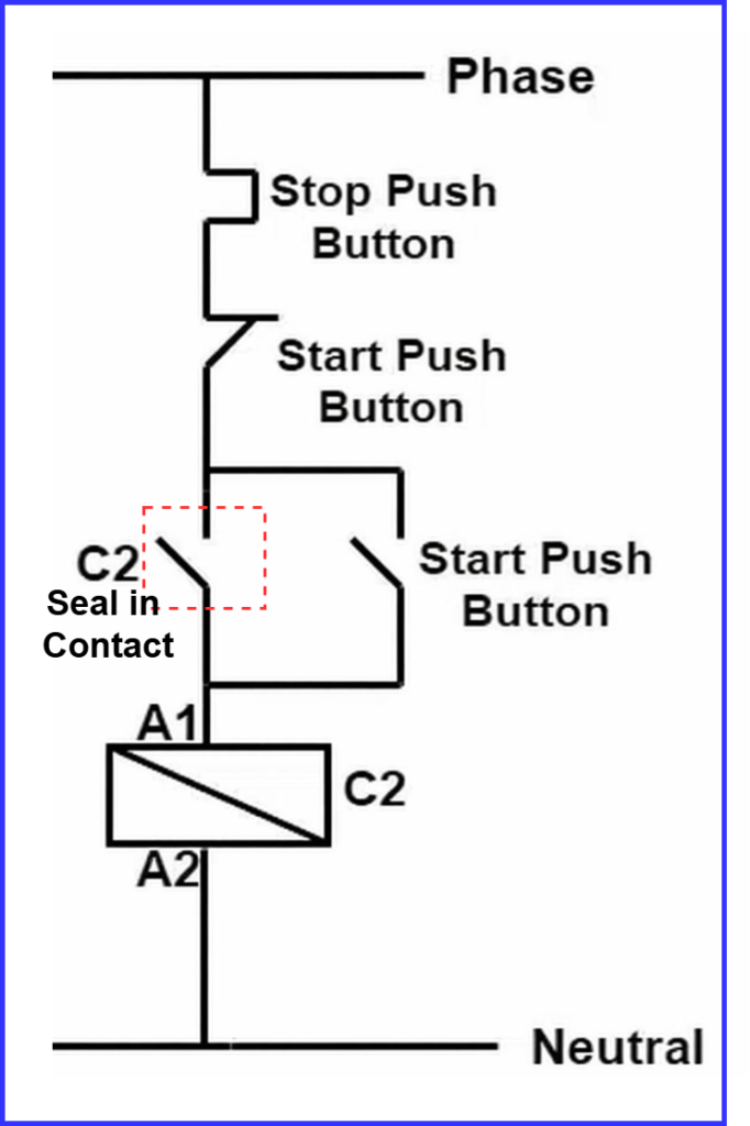
Seal-In Circuit Diagram (Basic Concept)
A standard seal in circuit diagram includes:
- Start push button (NO)
- Stop push button (NC)
- Relay or PLC output coil
- Seal-in contact connected in parallel with the Start button
In PLC systems, the same structure is implemented using ladder logic instead of physical wiring.
Seal-In Contact and Symbol
The seal-in contact is an auxiliary contact linked to the same output it controls.
When the output energizes, this contact closes and maintains the circuit.
The seal-in contact symbol is typically shown as a normally open contact associated with the same coil in wiring or ladder diagrams.
Seal-In Circuit Ladder Logic (PLC)
In PLC programming, the seal in circuit ladder logic replaces hardwired control with software logic.
A typical implementation uses:
- Start input (NO)
- Stop input (NC)
- Output coil
- Output contact as the seal-in contact
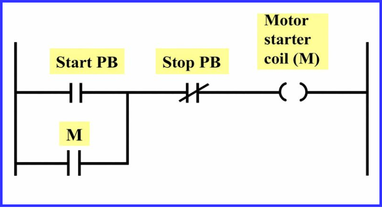
This logic is commonly referred to as:
- PLC latch circuit
- Latch circuit in PLC
- Latching circuit PLC
All terms describe the same holding principle.
Start-Stop Seal-In Circuit Example
The start–stop seal-in circuit, also known as a latching circuit, is the most widely used practical application of a seal-in circuit in industrial control systems. It allows an operator to start a machine with a momentary push button and keep it running continuously until a stop command is given.
Step-by-Step Operation
- Press Start Button
When the Start push button is pressed, the control circuit is completed, energizing the relay or motor starter coil. - Seal-In Action Occurs
As soon as the coil energizes, its auxiliary contact (seal-in contact) closes. This contact provides an alternate current path around the Start button. - Release Start Button
After the Start button is released, the circuit remains energized through the closed seal-in contact. The output stays ON without requiring continuous operator input. - Press Stop Button
When the Stop push button is pressed, the circuit is interrupted. Power to the coil is removed, the seal-in contact opens, and the output turns OFF.
Practical Applications
This control method is widely used because of its simplicity and reliability. Common applications include:
- Motor starters
- Pumps and compressors
- Conveyors and material handling systems
- Fans and blowers
- General industrial machinery
The start–stop seal-in circuit ensures safe, controlled operation by allowing intentional startup and shutdown while preventing accidental or unintended machine operation.
For designing, troubleshooting, or implementing seal-in circuits in real industrial environments, professional guidance can make a significant difference.
For expert assistance with control circuit design and PLC solutions, Contact FS Circuits.
Seal-In Relay vs PLC Latch Circuit
| Aspect | Seal-In Relay | PLC Latch Circuit |
| Control Method | Physical wiring | Software logic |
| Flexibility | Limited | High |
| Expansion | Difficult | Easy |
| Diagnostics | Manual | Program-based |
Despite the implementation difference, both follow the same seal-in logic.
Seal-In Circuit Instructions in PLCs
Typical seal in circuit instructions involve:
- Normally open and normally closed contacts
- Output coils
- Internal memory bits (for advanced logic)
While instruction names differ across PLC brands, the logic structure remains identical.
Conclusion
The seal in circuit is a fundamental building block of electrical and PLC control systems. By using a feedback seal-in contact, it creates a reliable latching function that keeps outputs energized until intentionally stopped. Whether implemented through a seal in circuit diagram, seal in circuit ladder logic, or a PLC latch circuit, the principle remains simple, safe, and effective. Understanding this concept is essential for anyone working in industrial automation and control systems.
Read Next: