PLC Logic Gates are the foundation of industrial automation and control systems. They allow a Programmable Logic Controller (PLC) to make decisions based on input conditions and execute output actions accordingly. From simple start-stop circuits to complex automation processes, PLC logic gates play a vital role in ladder programming and real-world industrial applications.
In this article, you will learn PLC Logic Functions, their ladder logic implementation, and how each logic gate works inside a PLC program using easy-to-understand explanations.
PLC Logic Functions
PLC logic functions are based on traditional digital logic gates used in electronics. However, in PLCs, these gates are implemented using ladder logic diagrams rather than electronic circuits.
Common logic gates in PLC include:
- AND
- OR
- NOT
- NAND
- NOR
- XOR
- XNOR
Each function processes one or more inputs to produce a single logical output.
PLC AND LOGIC
PLC AND logic produces an output only when all input conditions are TRUE. If two or more inputs are ON, the output turns ON. If any input is OFF, the output remains OFF.
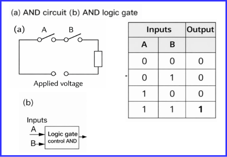
This arrangement can be viewed as a simple control system with two input signals, A and B (above figure). The system produces an output only when both inputs are active at the same time. In other words, the output turns ON only if A and B are ON together.
If we represent an ON condition by 1 and an OFF condition by 0, the output will be 1 only when A = 1 and B = 1. For all other combinations of inputs, the output remains 0.
This type of operation is governed by what is known as a logic gate. The behavior of a logic gate is defined by the relationship between its inputs and its output. This relationship is clearly shown using a table called a truth table. For an AND gate, the truth table lists all possible input combinations and the corresponding output states.
In a ladder logic diagram for AND gate, normally open contacts are connected in series. AND Gate Ladder Diagram Logic
- Input A = ON
- Input B = ON
- Output = ON
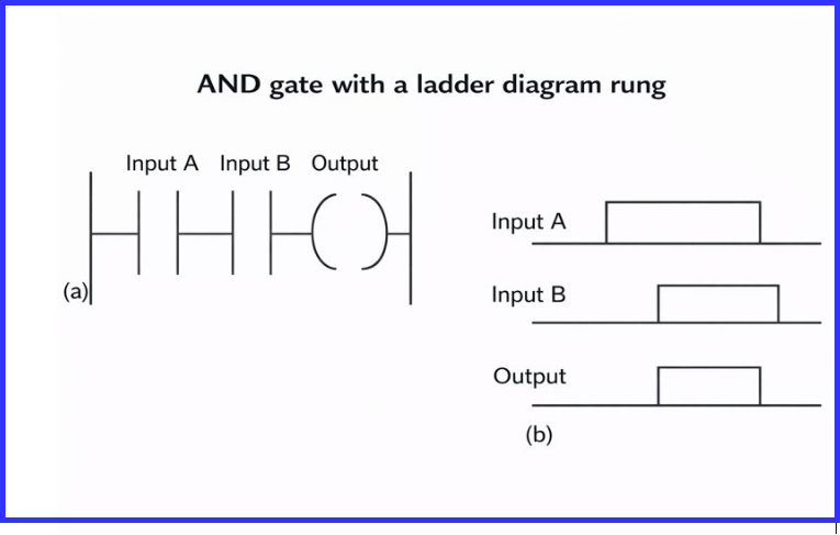
The ladder diagram begins with a normally open contact representing Input A, which corresponds to switch A. This contact is connected in series with another normally open contact labeled Input B, representing switch B. The rung ends with an output coil, which indicates the controlled output.
The output is energized only when both Input A and Input B are activated simultaneously. In practical terms, this means that the contacts for Input A and Input B must both be closed for the output to turn ON.
In general, a series connection of normally open contacts in a ladder diagram performs an AND logic function, where all input conditions must be true for the output to be energized.
This AND gate ladder diagram is widely used in safety interlocks, machine enabling conditions, and motor permissive circuits.
PLC OR LOGIC
PLC OR logic activates the output when any one of the inputs is TRUE. If at least one input is ON, the output turns ON.
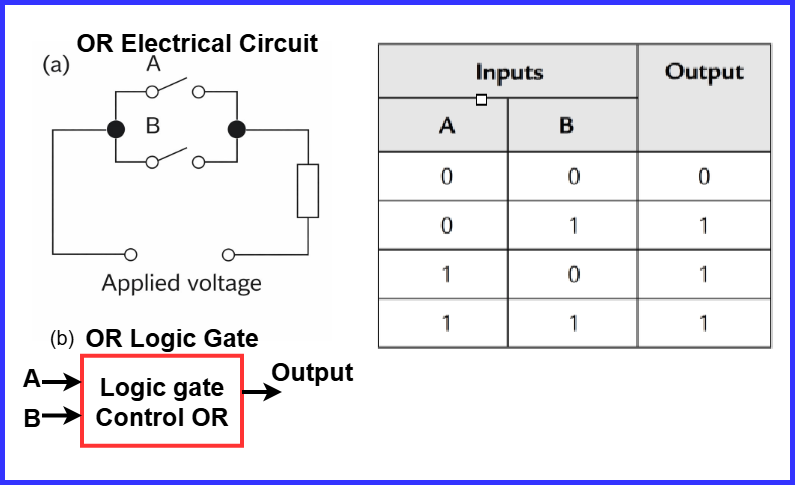
In the ladder diagram of logic gates, OR logic is implemented by connecting contacts in parallel.
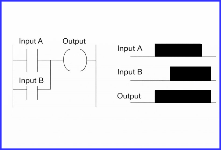
The ladder diagram begins with a set of normally open contacts labeled Input A, representing switch A. Connected in parallel with these contacts is another set of normally open contacts labeled Input B, representing switch B. Both contact sets lead to a single output coil at the end of the rung.
In this configuration, the output is energized when either Input A or Input B is activated. It is not necessary for both inputs to be closed at the same time—closing any one of them is sufficient to turn the output ON.
Key Concept: In ladder logic, parallel branches connected to the main rung indicate a logical OR operation. These alternative current paths allow the output to operate when at least one condition is satisfied.
A common real-world example of an OR gate in a control system is a conveyor belt used in bottle packaging. A deflector plate is triggered to reject a bottle if either of the following conditions occurs:
- The bottle weight is outside the acceptable range, or
- The bottle is missing its cap
If any one of these fault conditions is detected, the deflector activates, demonstrating classic PLC OR logic behavior.
Common Applications
OR logic is commonly used for:
- Multiple start buttons
- Alarm acknowledgment circuits
- Backup signal selection
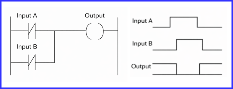
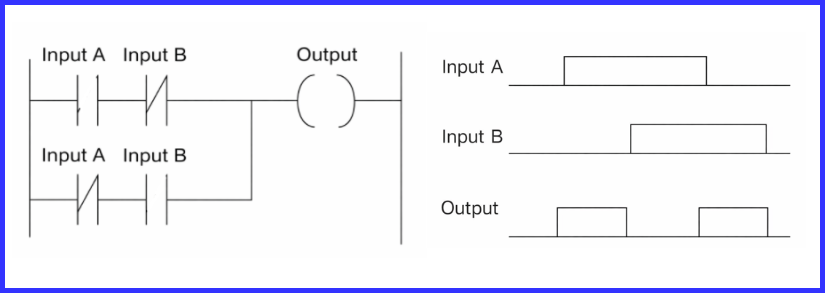
PLC NOT LOGIC
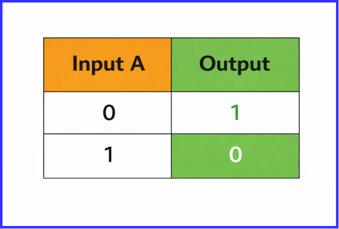
PLC NOT logic reverses the state of the input signal, meaning the output always behaves opposite to the input condition. When the input signal is ON, the output turns OFF, and when the input signal is OFF, the output turns ON. The NT gate truth table is:
The working principle of PLC NOT logic is simple and predictable. An active input blocks the output, while an inactive input allows the output to energize. This behavior makes NOT logic extremely useful in control systems where inverse actions are required.
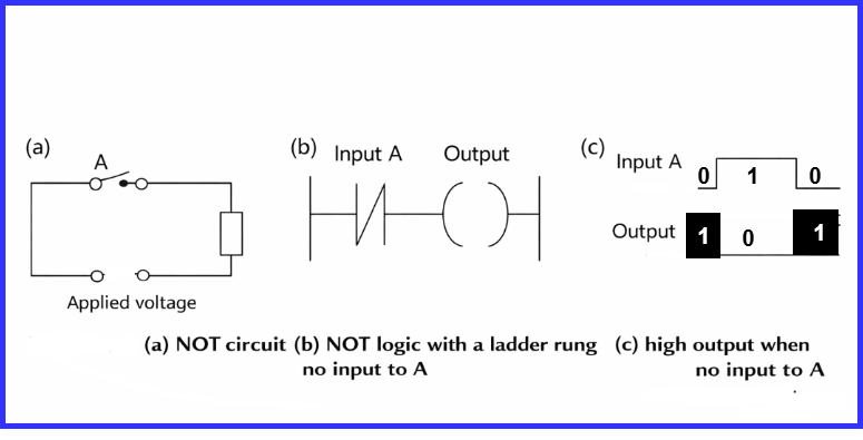
In ladder logic, NOT logic is implemented using a normally closed (NC) contact. The NC contact remains closed when the input is OFF and opens when the input turns ON, naturally creating the inversion effect.
PLC NOT logic is widely used in emergency stop circuits, fault detection systems, and fail-safe control logic. Because it ensures that equipment moves to a safe state when a signal is lost or a fault occurs, NOT logic is considered one of the most important PLC logic gates for safety-critical applications.
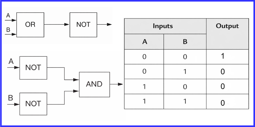
PLC NAND LOGIC
PLC NAND logic is the opposite of AND logic, meaning it produces an inverted output compared to a standard AND function.
The working principle of PLC NAND logic is straightforward. The output turns OFF only when all input conditions are ON at the same time. In every other input combination—when one or more inputs are OFF—the output remains ON.
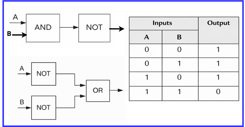
In ladder logic, NAND logic is implemented by first creating an AND logic circuit and then applying NOT logic to invert the result. This is typically done by using an AND condition followed by a normally closed (NC) contact or an output inversion.
PLC NAND logic is commonly used in alarm systems, safety shutdown circuits, and conditional blocking logic. Because the output stays active unless all conditions are satisfied, NAND logic is especially useful in applications where a fail-safe or warning condition must remain enabled by default.
PLC NOR LOGIC
PLC NOR logic is the inverse form of OR logic, meaning it produces an output only when none of the input conditions are active.
The working principle of PLC NOR logic is simple. The output turns ON only when all input signals are OFF. If any one of the inputs becomes ON, the output immediately turns OFF.
In ladder logic, NOR logic is implemented by first creating an OR logic circuit and then applying NOT logic to invert the result. This is typically achieved by using parallel input contacts followed by an output inversion or a normally closed condition.

PLC NOR logic is commonly used in applications where an output should activate only in the absence of all signals, such as standby systems, fault monitoring, and default-safe operating conditions.
PLC Exclusive OR (XOR) LOGIC
PLC XOR logic produces an output only when one input is TRUE and the other is FALSE. If both inputs are in the same state, the output remains OFF.
The working principle of PLC XOR logic is easy to understand. When Input A is ON and Input B is OFF, the output turns ON. Likewise, when Input A is OFF and Input B is ON, the output is also ON. However, if both inputs are ON or both are OFF, the output turns OFF.
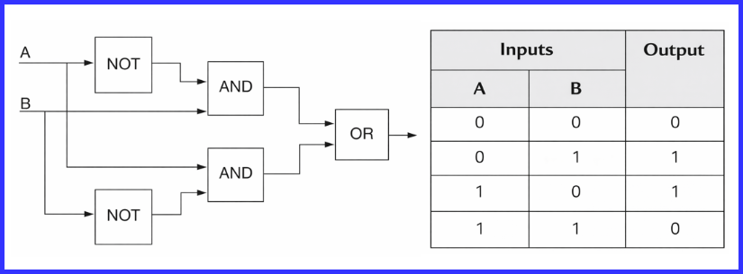
In ladder programming, XOR ladder logic is developed by combining AND, OR, and NOT instructions. This logical combination allows the PLC to detect unequal input conditions. The xor gate in ladder logic is commonly implemented using multiple rungs or intermediate memory bits.
PLC XOR logic is widely used in direction control systems, status comparison tasks, and conflict detection applications. Among the various logic gates in PLC, XOR logic is especially useful when the output must respond only to a difference between input states.
PLC Exclusive NOR (XNOR) LOGIC
PLC XNOR logic is the inverse of XOR logic, meaning it produces an output when the input conditions are equal.
The working principle of PLC XNOR logic is straightforward. The output turns ON when both inputs are in the same state, either both ON or both OFF. If the inputs differ, the output remains OFF.

In ladder logic, XNOR logic is implemented by first creating an XOR logic circuit and then applying NOT logic to invert the result. This combination allows the PLC to detect matching input conditions accurately.
PLC XNOR logic is commonly used for equality checking, synchronization monitoring, and process validation. It is especially useful in applications where the system must confirm that two signals or conditions are aligned before allowing further operation.
Ladder Diagram of Logic Gates in PLC
The ladder diagram of logic gates visually represents how PLC gates function using contacts and coils. Unlike electronic circuits, PLC ladder logic is easy to read, troubleshoot, and modify.
Benefits of ladder logic diagrams:
- Easy for electricians to understand
- Simple debugging
- Widely accepted industrial standard
Applications of PLC Logic Gates
PLC gates are used in almost every automation system, including:
- Motor control circuits
- Conveyor systems
- Pumps and compressors
- Packaging machines
- Safety interlocks
Whether simple or complex, logic gates in PLC form the backbone of industrial control logic.
Conclusion
PLC Logic Gates are essential building blocks of PLC programming and industrial automation. Understanding how AND, OR, NOT, NAND, NOR, XOR, and XNOR gates work in ladder logic helps engineers design reliable, safe, and efficient control systems. From basic motor starters to advanced automation processes, mastering PLC Logic Gates and ladder logic diagrams is a must for every PLC programmer and automation professional.
Read Next: