A split range control system is widely used in process industries when a single controller output is required to operate two or more final control elements in different operating ranges. This control strategy improves process flexibility, stability, and efficiency, especially in complex systems such as reactors, furnaces, and flare lines.
In this article, you will learn the working principle of split range control, its applications, dead band concept, pneumatic signal usage, and real-world examples.
What Is a Split Range Control System?
A split range control system is a control technique where the output of one controller is divided (split) into multiple signal ranges. Each range operates a different control valve, damper, or actuator.
Instead of using multiple controllers, one controller manages multiple outputs, but not simultaneously. Each device responds only within its assigned signal range.
Split Range Control Working Principle
The concept of split-range control is best understood through a temperature control application, where a process may require either heating or cooling depending on the product temperature. In such systems, the objective is to regulate temperature using one controller while ensuring that only the required action—heating or cooling—takes place at any given time.
The working principle of a split range control system is straightforward. A single process variable (PV), such as temperature, is continuously measured by a transmitter. This measured value is sent to the controller, where it is compared with the desired setpoint. Based on this comparison, the controller generates an output signal known as the controller output (CO).
Instead of sending this output to a single final control element, the controller output is divided into predefined ranges, with each range assigned to a different control valve. In a typical temperature control arrangement, the controller output spans from 0% to 100% and is split between a cooling valve and a heating valve.
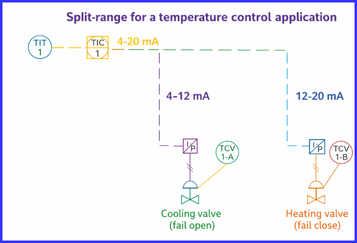
When the controller output falls within the lower range, only the cooling valve responds. For example, when the output is between 0% and 50%, the cooling valve operates, remaining fully open at the lower end of the range and gradually closing as the output approaches the midpoint. Once the controller output reaches 50%, the cooling valve is completely closed.
As the controller output increases beyond this midpoint, the upper range becomes active and the heating valve begins to operate. The heating valve starts opening at 50% controller output and continues to open until it reaches the fully open position at 100% output. This ensures that heating and cooling never occur simultaneously.
In practical installations, this split operation is often implemented using current-to-pressure (I/P) converters. The controller output current is divided so that one converter responds to 4–12 mA and drives the first valve, while the second converter operates in the 12–20 mA range and controls the second valve. As a result, only one valve moves at a time, depending on the magnitude of the controller output.
With this method of signal splitting, no special controller or complex configuration is required. Standard controllers can easily implement split-range control through proper calibration of the output ranges and final control elements.
Split Range Control Using Pneumatic Signals
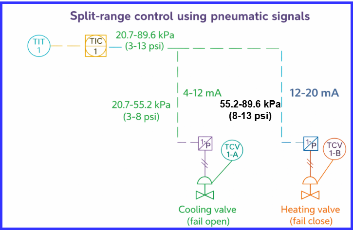
The arrangement shown in the figure illustrates the same split-range control concept, but here the controller output is a pneumatic signal rather than an electrical one. In pneumatic control systems, split-range operation is commonly implemented using the standard 3–15 psi signal range, which is widely accepted across process industries.
In this setup, the two control valves are mechanically configured differently so that each valve responds within a specific portion of the pneumatic signal. The spring–diaphragm actuators are selected to create distinct operating ranges for the valves, allowing the controller output to be divided naturally without additional signal-splitting devices.
Typically, the first control valve operates in the lower pressure range, such as 3–9 psi, while the second control valve responds to the higher range of 9–15 psi. For example, the cooling valve may be designed to open and close between 20.7 kPa (3 psi) and 55.2 kPa (8 psi). Once this pressure is reached, the cooling valve becomes fully closed and remains inactive. As the controller output pressure increases beyond this point, the heating valve begins to operate, opening over a range of 55.2 kPa (8 psi) to 89.6 kPa (13 psi).
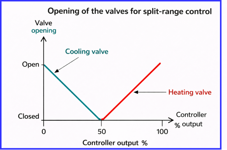
The opening and closing sequence of the valves follows the same operating logic as electrical split-range systems, ensuring that only one valve is active at a time. A characteristic graph is often used to show the relationship between controller output pressure and valve position, clearly highlighting the transition from one valve to the other.
The graph illustrates how the valve positions change in response to the controller output.
Pneumatic split-range control is preferred in many installations because pneumatic signals are highly reliable in hazardous environments, intrinsically safe, easy to calibrate, and well suited for high-temperature areas. Due to these advantages, split-range pneumatic control is extensively used in oil and gas facilities, refineries, and chemical processing plants.
Dead Band for Split Range Control
The arrangements discussed earlier represent some of the simplest implementations of split-range control. In real industrial applications, modern controllers can support more refined split-range configurations and overcome certain limitations found in basic setups.
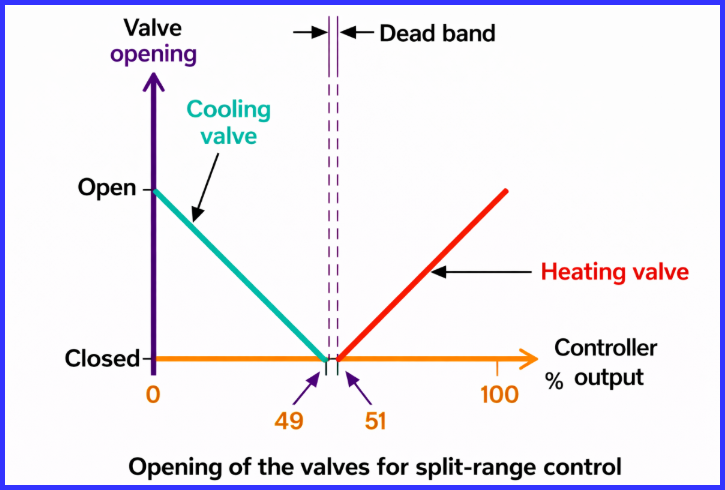
One common challenge with simple split-range control is the tendency of the system to rapidly switch between heating and cooling when the controller output remains close to the changeover point. This behavior, often referred to as hunting, can cause unstable operation, excessive valve movement, and accelerated mechanical wear.
To eliminate this problem, a dead band is introduced between the two split ranges. A dead band is a small neutral zone where neither control valve responds to changes in the controller output. By creating this inactive region, the system avoids simultaneous valve movement and ensures a smooth transition from one control action to the other.
For example, in a pneumatic split-range system, one valve may be designed to operate between 3 and 8.8 psi, while the second valve responds from 9.2 to 15 psi. The pressure range between 8.8 and 9.2 psi forms the dead band, during which both valves remain stationary.
This arrangement prevents oscillation, improves overall system stability, and significantly reduces mechanical stress on the final control elements.
Dead band implementation is particularly critical in high-accuracy temperature and pressure control applications, where even small fluctuations can impact product quality or process safety.
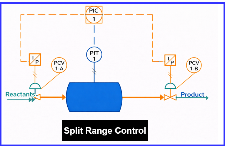
Using Split-Range to Control the Input and Output of a Reactor
The figure below illustrates another practical application of split-range control in a chemical reactor system. In this arrangement, reactants enter the reactor through an inlet control valve that regulates the incoming flow, while a second control valve at the outlet controls the discharge rate.
To maintain high reaction efficiency and ensure uniform product quality, key process variables inside the reactor—such as pressure and temperature—must be carefully controlled. A pressure or temperature transmitter continuously monitors the reactor conditions and sends the signal to a single controller configured for split-range operation.
In pressure control mode, when the reactor pressure drops below the desired value, the controller initially opens the inlet valve to increase the internal pressure. If the pressure remains low, the controller further responds by closing the outlet valve, allowing pressure to build up inside the reactor.
Similarly, in reactor temperature control, split-range control allows both heating and cooling to be managed using one temperature controller. When the controller output lies in the lower range, the cooling valve opens to remove excess heat. As the controller output moves into the higher range, the cooling action stops and the heating valve begins to open, raising the reactor temperature as required. This ensures that heating and cooling never occur simultaneously.
The graph below shows how the positions of the control valves vary with the controller output, clearly demonstrating how split-range control coordinates multiple final control elements using a single signal.
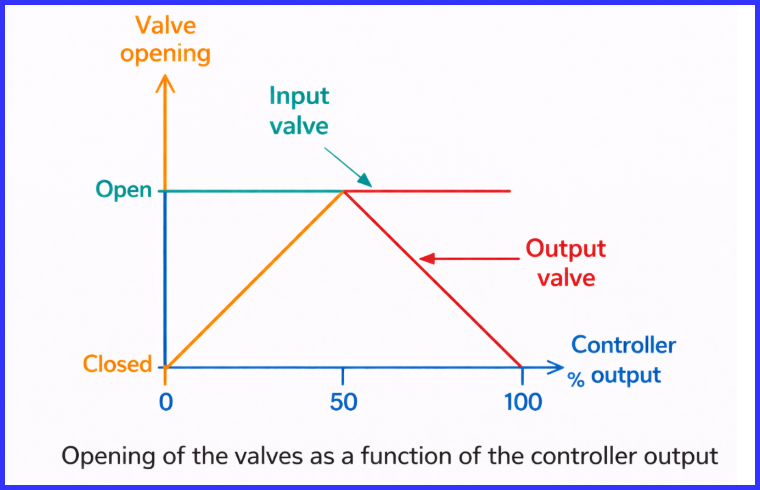
In some installations, the controller may be configured to allow overlapping valve operation around the midpoint of the output range. For example, the outlet valve may be fully open at 0% controller output, both valves may be partially open at 50%, and at 100% output, the inlet or heating valve becomes fully open while the outlet or cooling valve is fully closed. This overlap can provide smoother control during load changes.
By using split-range control in reactor applications, plants benefit from smooth temperature regulation, faster response to disturbances, no need for controller switching, and improved product consistency. For this reason, split-range control is widely applied in both batch and continuous reactor systems.
Split-Range Control for a Flare Application
Gas flares are widely used in refineries and chemical processing plants as a vital safety measure. Their main function is to safely dispose of excess flammable gases from vessels and pipelines, thereby preventing dangerous over-pressure situations that could otherwise result in explosions. During abnormal or upset conditions, the flare system acts as a critical safeguard, protecting both personnel and equipment.
To achieve controlled and efficient pressure relief, many flare systems employ split-range control. This strategy allows a single controller to regulate multiple valves in a coordinated manner, ensuring safe operation across varying pressure conditions.
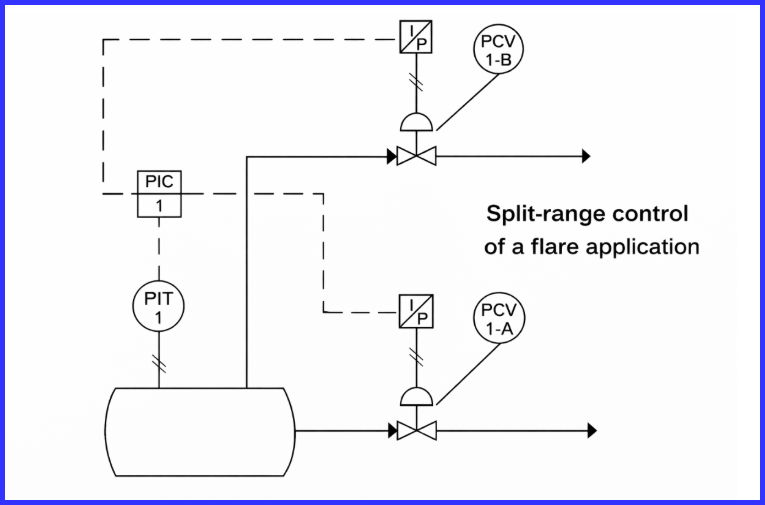
In a typical flare application, process fluids or gases are handled inside a vessel where chemical or physical processes produce the desired product along with an unavoidable excess of combustible gas. A pressure transmitter continuously monitors the vessel pressure and sends this signal to a controller configured for split-range operation. Based on the measured pressure, the controller determines the appropriate corrective action.
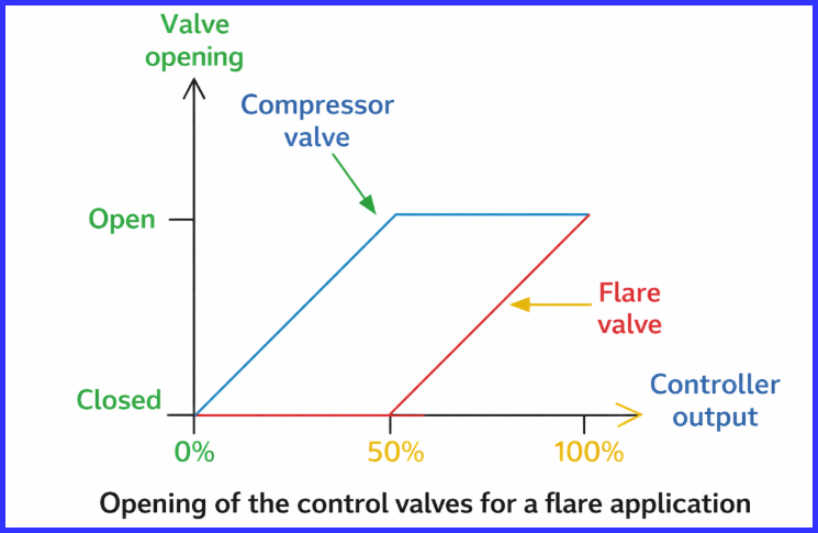
When the pressure rise is small, the controller first opens a recycle or product outlet valve, allowing gas to flow toward a compressor or recovery system. This action helps maintain vessel pressure while minimizing flaring and conserving valuable fuel. As the controller output increases to the mid-range, the recycle valve becomes fully open while the flare valve remains closed.
If the pressure continues to rise and exceeds safe limits, the controller output moves into the higher range, causing the flare valve to open. This directs the excess gas to the flare stack for safe combustion. Under maximum pressure conditions, both the recycle valve and the flare valve are fully open, ensuring rapid and safe pressure relief.
By using split-range control in flare systems, plants can reduce unnecessary emissions, improve environmental compliance, and enhance overall safety, while still maintaining effective pressure control. This approach ensures that flaring occurs only when absolutely necessary, making it an efficient and environmentally responsible control strategy.
Advantages of Split Range Control System
- Uses a single controller for multiple outputs
- Reduces control hardware cost
- Improves process flexibility
- Provides smooth transition between control elements
- Ideal for heating–cooling and pressure applications
Limitations of Split Range Control
- Requires accurate calibration
- Improper dead band can cause instability
- Not suitable where simultaneous control is required
- Initial setup is more complex
Applications of Split Range Control System
- Reactor temperature control
- Furnace draft control
- Flare pressure management
- Compressor surge control
- Flow and level control systems
Conclusion
A split range control system is an efficient and intelligent control strategy that allows a single controller to manage multiple final control elements over different operating ranges. By using techniques such as pneumatic split signals, dead band, and proper calibration, split range control enhances process stability, safety, and operational efficiency. It is especially valuable in reactors, flare systems, and temperature control applications where precise and flexible control is essential.
Read Next: