Interlocking in PLC is a fundamental concept used in industrial automation to ensure that only one operation occurs at a time under defined conditions. It is mainly implemented to improve safety, reliability, and correct sequencing of machines and processes. In simple terms, interlocking prevents one output from turning ON unless certain conditions are satisfied, and it blocks conflicting operations from happening together.
This article explains the concept of interlocking in PLC, its working principle, advantages, applications, and a clear ladder logic example using a go-down wiring system for three rooms.
What Is Interlocking in PLC?
Interlocking in PLC refers to a control logic technique where the operation of one device depends on the status of another device. The PLC uses interlock conditions to allow or restrict outputs based on predefined rules.
For example, a motor may not start unless another motor is OFF, or a valve may open only when a pump is running. This logic ensures safe and orderly operation.
Interlocking is commonly implemented using:
- Normally Open (NO) contacts
- Normally Closed (NC) contacts
- Output feedback contacts
- Internal PLC memory bits
Why Interlocking Is Required in PLC Systems
Interlocks in PLC are essential for many reasons:
- To avoid equipment damage
- To prevent unsafe operating conditions
- To ensure correct sequence of operation
- To reduce human error
- To improve system reliability
Without proper PLC interlocking, machines may operate simultaneously in conflicting ways, leading to accidents or failures.
PLC Interlocking Concept Explained Using Go-Down Wiring
A go-down wiring system is a classic and simple example to understand the interlock in PLC logic. It is commonly used in staircases, corridors, or warehouses where only one light should remain ON at a time.
System Description
Inputs (Toggle Switches):
- I0.0 → Room 1 switch
- I0.1 → Room 2 switch
- I0.2 → Room 3 switch
Outputs (Bulbs):
- Q0.0 → Room 1 bulb
- Q0.1 → Room 2 bulb
- Q0.2 → Room 3 bulb
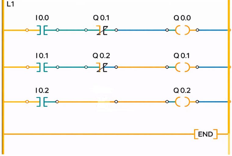
Simple Interlock Circuit Logic (Ladder Diagram Conceptual)
This system is designed so that:
- Only one room light remains ON at a time
- Switching ON the next room automatically switches OFF the previous one
- Reverse movement restores lights in the opposite direction
This is achieved using NC interlock contacts of other outputs in each rung.
Working of Interlocking in PLC (Step-by-Step)
Step 1: Room 1 Operation
When a person enters Room 1 and turns ON toggle switch I0.0, the PLC energizes output Q0.0, and the bulb in Room 1 glows.
Step 2: Moving to Room 2
If the person moves to Room 2 without switching OFF Room 1 and presses I0.1, output Q0.1 turns ON.
At the same time, the NC interlock contact of Q0.1 in the Room 1 rung opens, breaking the circuit and switching Q0.0 OFF.
This ensures that Room 1 light goes OFF when Room 2 light turns ON.
Step 3: Moving to Room 3
When I0.2 is pressed in Room 3, output Q0.2 is energized.
The interlock contact of Q0.2 breaks the Room 2 circuit, switching Q0.1 OFF, while Room 3 light remains ON.
This demonstrates downward movement interlocking.
Reverse Operation (Coming Back)
Step 4: Switching OFF Room 3
When the person presses I0.2 again, output Q0.2 turns OFF.
Since the interlock contact is now restored, Room 2 light (Q0.1) turns ON automatically.
Step 5: Switching OFF Room 2
Pressing I0.1 again switches OFF Q0.1.
The interlock contact returns to its normal state, allowing Room 1 light (Q0.0) to turn ON.
Step 6: Switching OFF Room 1
Finally, pressing I0.0 switches OFF Q0.0, and all lights go OFF.
This completes the full go-down interlocking sequence.
Types of Interlocks in PLC
- Electrical Interlocking – Uses output feedback contacts
- Software Interlocking – Uses PLC logic and internal bits
- Safety Interlocking – Uses safety relays or safety PLCs
- Sequence Interlocking – Controls step-by-step operations
Advantages of Interlocking in PLC
- Prevents conflicting operations
- Enhances personnel and equipment safety
- Reduces wiring complexity
- Easy to modify through software
- Improves system reliability
Applications of PLC Interlocking
- Go-down lighting systems
- Motor forward–reverse control
- Conveyor sequencing
- Boiler and burner management systems
- Pump and valve interlocks
- Machine safety systems
Conclusion
Interlocking in PLC is a vital control technique used to ensure safe, reliable, and sequential operation of industrial systems. By using PLC interlocks, designers can prevent simultaneous or unsafe operations without complex wiring. The go-down wiring example clearly demonstrates how interlocking in PLC works using simple ladder logic and output feedback contacts. Proper implementation of interlocks improves safety, reduces failures, and makes automation systems more efficient and intelligent.
Read Next: