A control loop is the core of automation and process control systems. It continuously measures a process variable, compares it with a desired set point, and applies corrective action to keep the process within acceptable limits. Control loops are widely used in instrumentation, industrial automation, and control engineering.
Control Loop Definition
A control loop is a closed system that automatically regulates a process variable by measuring the output, comparing it with a set point, and adjusting the input through a control element.
In instrumentation, a control loop consists of a sensor, controller, final control element, and process, connected in a continuous path.
How a Control Loop Works
A control loop operates as a continuous cycle:
- The sensor measures the process variable
- The controller compares the measurement with the set point
- Any deviation is converted into a corrective signal
- The final control element adjusts the process
This feedback-based operation allows the system to maintain stability even when disturbances occur.
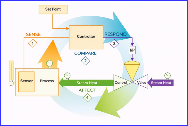
Control Loop Operating Steps
Sense:
The control loop begins by monitoring the actual condition of the process. A sensing element such as a thermocouple or RTD, often connected to a transmitter, measures the process variable (for example, temperature) and converts it into a usable signal.
Compare:
This signal is sent to the controller, where it is continuously compared with the desired set point. An electronic PID controller evaluates the difference between the measured value and the set point to determine whether the process is operating within acceptable limits.
Respond:
When a deviation or error is detected, the controller responds by generating an appropriate corrective output signal. This signal represents the magnitude and direction of the adjustment required to bring the process variable closer to the set point.
Affect:
The corrective signal is then applied to the final control element, typically a control valve. The valve changes its position to modify the process conditions, such as regulating the flow of heating or cooling media, which directly influences the process variable.
This sequence operates continuously in a closed loop, repeatedly sensing, comparing, responding, and affecting the process until the variable stabilizes at the desired set point and remains within controlled limits.
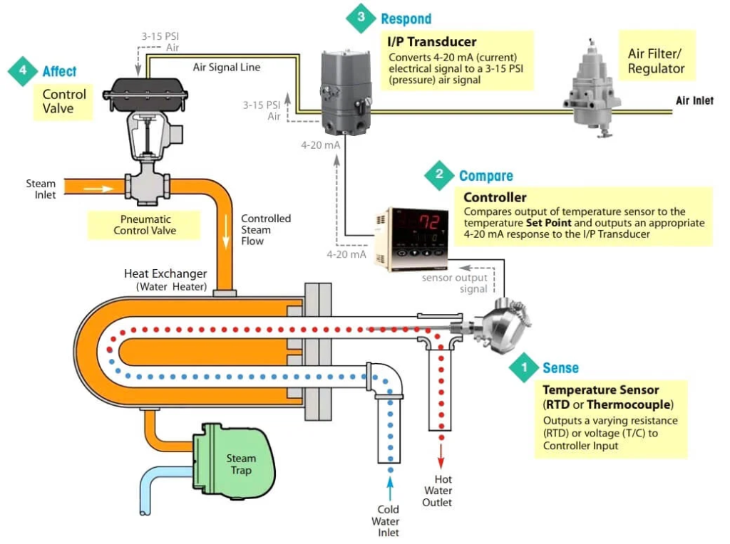
Image Credits : watsonmcdaniel.com
Main Components of a Control Loop
A typical components includes:
- Sensor / Transmitter: Measures the process variable (temperature, pressure, flow, or level) and sends a standardized signal to the controller.
- Controller: Compares the measured value with the set point and calculates the corrective action, typically using PID control.
- Final Control Element: Executes the controller output by adjusting the process, such as opening a control valve or changing motor speed via a VFD.
- Process: The physical system being controlled, such as a heat exchanger, tank, or pipeline.
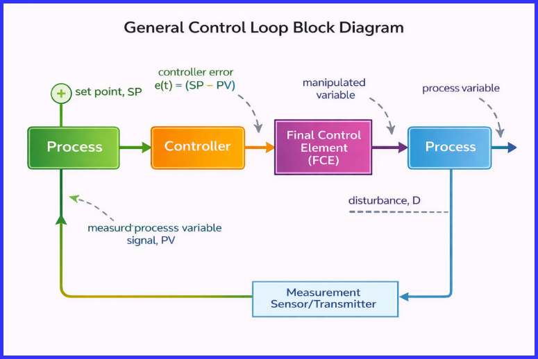
Control Loop Block Diagram (Concept)
A control loop diagram represents the signal flow as:
Process → Measurement → Control → Correction → Process
This closed path continues until the process variable matches the set point.
Types of Control Loops
Different applications use different types of control loops, including:
- Open loop control: Operates without feedback and does not measure the output. It is simple in design but less accurate and cannot correct disturbances.
- Closed loop control: Uses feedback to compare the output with the set point, allowing accurate and stable regulation of the process.
- Feedback control loop: Continuously monitors the process output and automatically corrects deviations to maintain the desired set point.
- Feedforward control loop: Predicts and compensates for disturbances before they impact the process, resulting in faster response.
- Process control loop: Widely used in industrial plants to control variables such as flow, level, pressure, and temperature.
Control Loop Examples
Heat Exchanger Control Loop Example
In a heat exchanger control loop:
- A temperature sensor measures outlet temperature
- The controller compares it with the set point
- An I/P converter drives a pneumatic control valve
- Steam flow is adjusted until the target temperature is reached
This is a standard industrial process control loop.
Level Control Loop
A level transmitter senses liquid level, the controller evaluates the signal, and a valve adjusts inflow or outflow to maintain the desired level.
Control Loop in P&ID and Instrumentation
In P&ID drawings, control loops are shown using standardized symbols and loop numbers to indicate instrument connections and control logic. In instrumentation systems, control loops ensure reliable operation, consistent product quality, energy efficiency, and process safety.
Condition Controlled Loop
A condition controlled loop regulates a process based on a specific condition such as temperature, pressure, or level and takes corrective action only when deviation occurs.
Advantages of Control Loops
- Automatic and continuous control
- High accuracy and repeatability
- Improved safety
- Reduced manual intervention
- Stable and efficient process operation
Conclusion
A control loop is a fundamental part of control systems and industrial automation. By combining measurement, comparison, and correction into a closed system, control loops maintain process variables at their desired values. Understanding what is a control loop, its types, and practical examples helps engineers design efficient, safe, and reliable control systems.
Read Next: