A Traffic Lights Ladder Diagram is one of the most common and beginner-friendly examples used to understand PLC programming concepts. Traffic control systems are widely implemented using PLCs because they offer reliability, flexibility, and easy modification of timing sequences. By studying a traffic light ladder diagram, learners can clearly understand how timers, outputs, and logical sequencing work together in a real-world application.
In this article, we will explain the ladder diagram traffic light system using PLC timers in a simple and structured way. The explanation includes inputs and outputs, ladder logic for traffic light operation, program description, and testing methodology.
Traffic Lights
Traffic lights are automatic signaling devices installed at road intersections to control vehicle movement and ensure safety. A standard traffic signal consists of three lamps:
- Red light – Stop
- Yellow light – Ready or caution
- Green light – Go
In PLC-based systems, these lights are controlled by predefined timing logic. The traffic light PLC ladder diagram ensures that each light turns ON and OFF in a proper sequence using timers.
PLC Program for Traffic Light
Before developing the traffic light ladder diagram, it is important to define the inputs and outputs.
Inputs
In a basic traffic light PLC program, physical inputs may be minimal or optional:
- Start push button
- Stop push button (optional)
- Power supply signal
Outputs
The outputs represent the traffic signal lamps:
- Red Light
- Yellow Light
- Green Light
Each output is controlled by PLC ladder logic and activated for a specific duration using timers.
Ladder Diagram Using Timers For Traffic Lights
The ladder logic traffic light system primarily relies on ON-delay timers (TON). Each timer controls how long a particular light remains ON.
Basic Timer Sequence
- Green light turns ON for a preset time
- Yellow light turns ON after green light turns OFF
- Red light turns ON after yellow light turns OFF
- The cycle repeats continuously
This sequence is implemented in the traffic signal PLC program using multiple timers arranged in series.
Program Description
The working of the traffic lights ladder diagram using timers is explained step by step below:
A normally open (NO) contact is used for the Start push button (I0.0) to initiate the traffic light sequence.
Rung 0 – Green Light
- The normally open Start button (I0.0) energizes the Green output (Q0.0).
- A TP (pulse) timer is used to keep the green light ON for a predefined time.
- After the timer expires, the green output turns OFF automatically.
Rung 1 – Yellow Light
- The normally open Start button (I0.0) activates the Yellow output (Q0.1).
- A TON (on-delay) timer delays the activation of the yellow light.
- A TP timer then turns ON the yellow light for a fixed duration.
Rung 2 – Red Light
- The normally open Start button (I0.0) triggers the Red output (Q0.2).
- A TON timer delays the red light activation to maintain proper sequence.
- A TP timer keeps the red light ON for a preset time before the cycle repeats.
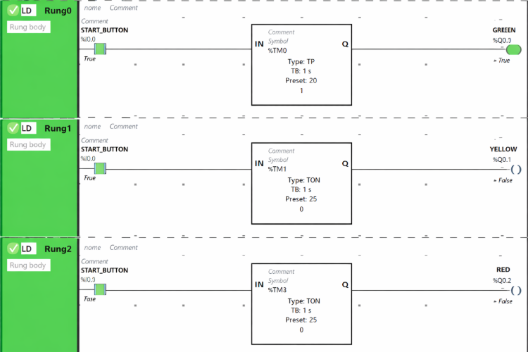
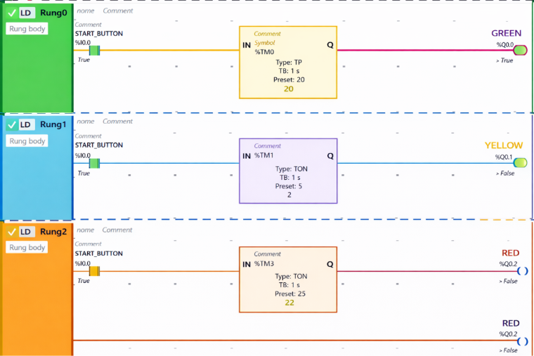
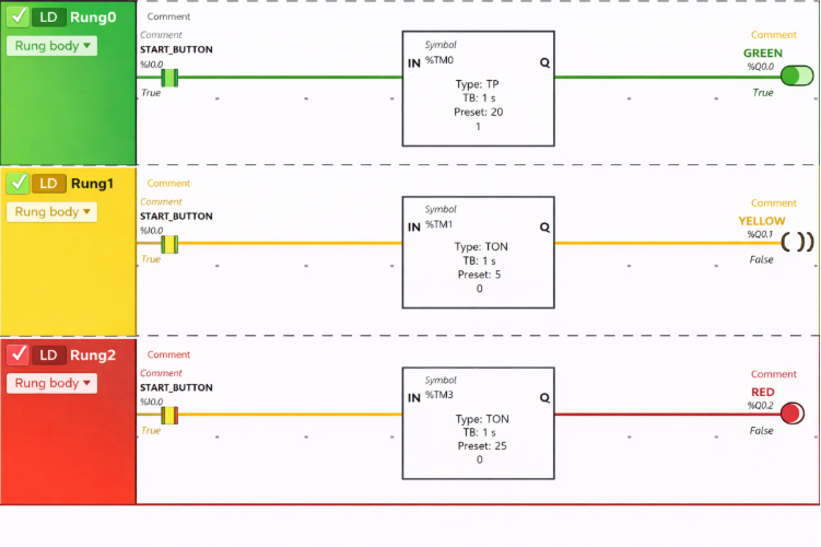
Program Testing
Testing the traffic light ladder diagram is an important step before real-world implementation.
Testing Steps
- Run the program in PLC simulation mode.
- Verify that only one light is ON at a time.
- Check timer preset values for correct delay.
- Ensure the sequence follows Green → Yellow → Red.
- Observe continuous and stable operation without faults.
Proper testing confirms that the traffic signal circuit diagram logic functions correctly and safely.
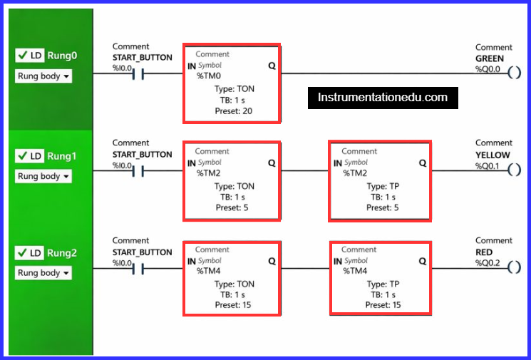
Rung 0:
When the Start Button (I0.0) is pressed, the current passes through it because the Start Button is configured as a Normally Open (NO) contact.
The Green output (Q0.0) is activated for 20 seconds since a TP (Pulse Timer) function block is used, which allows the output to remain ON for a specified duration. Once the 20-second interval elapses, the Green output (Q0.0) automatically switches OFF.
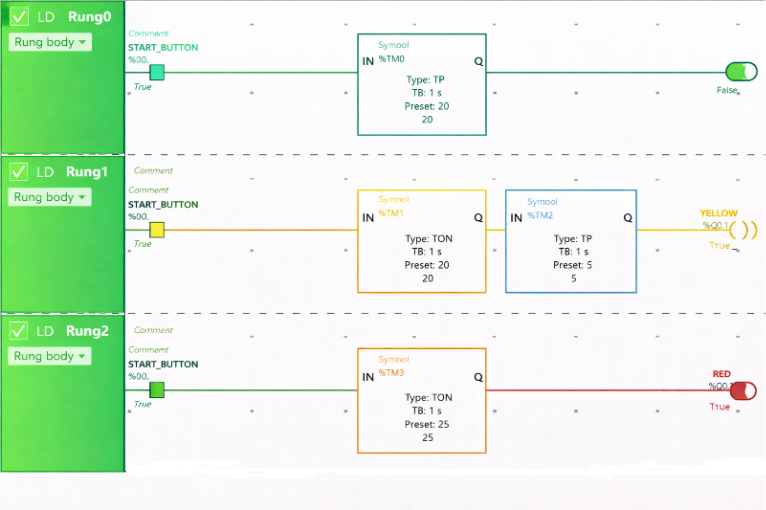
Rung 1:
When the Start Button (I0.0) is pressed, the Yellow output (Q0.1) switches ON after a delay of 20 seconds—that is, right after the Green output (Q0.0) turns OFF. This delay is achieved using a TON (On-Delay Timer) function block, which postpones the activation of the Yellow output (Q0.1) for the preset time of 20 seconds.
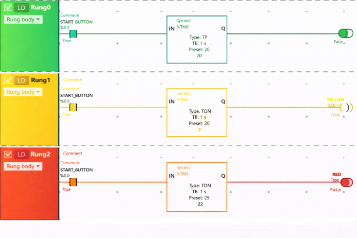
The Yellow output (Q0.1) stays ON for just 5 seconds because a TP (Pulse Timer) function block is used, which limits the ON duration. Once the 5-second timer expires, the Yellow output (Q0.1) automatically turns OFF.

Rung 2:
When the Start Button (I0.0) is pressed, the Red output (Q0.2) is activated after a 25-second delay—that is, right after the Yellow output (Q0.1) switches OFF. This delay is implemented using a TON (On-Delay Timer) function block, which postpones the activation of the Red output (Q0.2) for the preset time of 25 seconds.
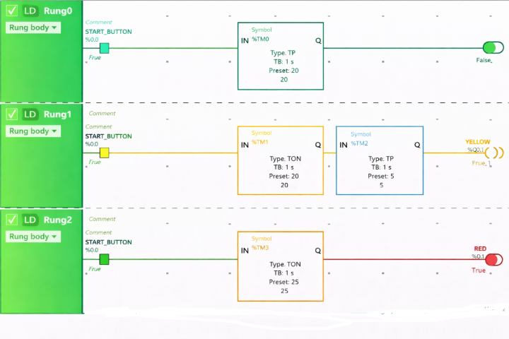
The Red output (Q0.2) turns ON after a 25-second delay. It remains active for only 15 seconds because a TP (Pulse Timer) function block is used, which restricts the ON duration. Once the 15-second period ends, the Red output (Q0.2) automatically switches OFF.
Conclusion
The Traffic Lights Ladder Diagram using timers is an excellent example for understanding PLC sequencing and timer operations. It demonstrates how simple ladder logic can control real-life systems efficiently. By mastering the ladder logic for traffic light, learners can easily move toward complex PLC automation projects such as industrial conveyors, batch processes, and plant control systems.
A well-designed traffic light PLC ladder diagram ensures safe, reliable, and systematic traffic control, making it a foundational exercise in PLC programming.
Read Next: