Spool valves are widely used in hydraulic and pneumatic systems to control the direction, flow, and pressure of fluids. Understanding the types of spool valve is essential for engineers and technicians working in automation, hydraulics, and fluid power systems. These valves are known for their precise control, compact design, and reliable operation in demanding industrial environments.
In this article, you will learn what is a spool valve, how it works, different spool valve types, construction details, configurations, and real-world applications.
What is a Spool Valve?
A spool valve is a type of directional control valve that uses a precisely machined cylindrical or rotating element, known as a spool, to regulate the flow of hydraulic or pneumatic fluid within a system.
The spool contains raised lands and is designed to slide smoothly inside a close-fitting bore of the valve body, with radial clearance typically less than 0.02 mm, ensuring accurate control and minimal internal leakage.
As the spool shifts or rotates within the valve body, its lands open, close, or redirect internal ports to create different flow paths. This controlled movement allows the valve to start, stop, or change the direction of fluid flow.
In spool valve hydraulic systems, this functionality is essential for operating actuators such as cylinders and hydraulic motors. Due to their precision, reliability, and flexibility, spool type valves are widely preferred in both industrial automation and mobile hydraulic applications.
What Does a Spool Valve Do?
A spool valve plays a key role in controlling the behavior of fluids in hydraulic and pneumatic systems. Its primary function is to manage how fluid flows through the system by selectively opening and closing internal passages as the spool moves within the valve body.
A spool valve performs the following functions:
- Directs fluid flow to different ports:
By shifting the spool position, the valve routes fluid to specific ports, allowing it to reach the required actuator or return to the tank. - Starts or stops fluid movement:
The spool can block or allow fluid flow, effectively turning the system ON or OFF as needed during operation. - Controls actuator direction:
Spool valves determine whether an actuator, such as a hydraulic cylinder, extends or retracts by changing the direction of fluid flow. - Regulates system pressure and flow paths:
Depending on the valve configuration, the spool helps maintain proper pressure levels and ensures smooth, controlled fluid circulation within the system.
In hydraulic systems, hydraulic spool valves are widely used to control pumps, cylinders, and hydraulic motors. In motor spool applications, they allow precise control of motor speed and direction, making them essential components in industrial machinery, mobile equipment, and automated systems.
Types of Spool Valve
Based on movement and design, there are two types of spool valves used in fluid control systems.
1. Rotary Spool Valve
A rotary spool valve controls fluid flow by rotating the spool inside the valve body, allowing internal passages to align with or block the connected ports. Unlike sliding designs, the spool turns about its axis to open or close the fluid paths, ensuring smooth and controlled operation.
Key Features:
- Spool rotates instead of sliding
- Smooth operation with low friction
- Compact and simple design
- Suitable for low-pressure and small flow-rate applications
- Usually manually operated
Applications:
- Machine tools industry
- Automotive systems
- Fuel control systems
- Industrial fluid routing
Because of their reliability and ease of operation, rotary spool valves are commonly selected where precise fluid control is needed without the complexity of high-pressure systems.
2. Sliding Spool Valve
Sliding spool valves are the most commonly used spool type valves in industrial and hydraulic systems. A sliding spool valve operates through the linear movement of the spool within the valve body, allowing precise opening and closing of internal flow passages. Due to this simple yet effective mechanism, these valves offer high accuracy, reliability, and excellent control over fluid direction.
Designed to handle high flow rates and high operating pressures, sliding spool valves are suitable for a wide range of control systems, from basic circuits to complex hydraulic networks.
Key Features:
- Linear movement of the spool inside the valve body
- Most common spool type valve used in industry
- High accuracy and dependable performance
- Suitable for high-pressure applications
Applications:
- Hydraulic presses
- Construction and earthmoving equipment
- Industrial automation systems
Their adaptability and robust construction make sliding spool valves a preferred choice in demanding industrial environments.
Construction of Spool Valve
These valves use a precisely machined cylindrical shaft, known as a spool, which moves linearly inside a close-fitting bore within the valve body. The valve body contains multiple inlet, outlet, and return ports that connect the directional control valve to the hydraulic circuit and allow controlled fluid entry and exit.
The basic construction of a spool valve consists of:
- Valve body – Houses the flow passages and ports
- Spool – A cylindrical element with carefully designed lands and grooves
- Actuation mechanism – Manual lever, solenoid, pneumatic, or hydraulic actuation
- Seals and springs – Provide leak-free operation and return the spool to its default position
Sliding spool–type directional control valves can be manufactured using different combinations of valve spool types and housing designs. The raised lands on the spool divide the bore of the valve body into a series of isolated chambers. The ports in the valve body open into these chambers, and the relative position of the spool determines how the ports are interconnected. Variations in spool land geometry define how and when fluid paths open or close.
Due to this flexible design, spool-type valves are widely used in mobile hydraulic systems. They can be easily shifted into two, three, or multiple positions, allowing fluid to be directed between different combinations of pressure, actuator, and tank ports.
Based on their flow behavior in the neutral position, sliding spool valves commonly use four standard center configurations:
- Closed center
- Open center
- Tandem center
- Float center
Although many other configurations are available, these basic designs cover most industrial and mobile hydraulic applications.
In typical operation, shifting the spool to the left connects the pressure port (P) to port A and routes port B to the tank (T). When the spool is shifted to the right, the flow paths reverse, connecting P to B and A to T, thereby controlling the direction of actuator movement.
Two-position Directional Control Valves
The figure illustrates a four-way, two-position directional control valve of the sliding spool type, manually operated by a lever and returned to its normal position by a spring. Two-position valves have two fixed spool positions, making them well suited for simple ON/OFF control in hydraulic systems.
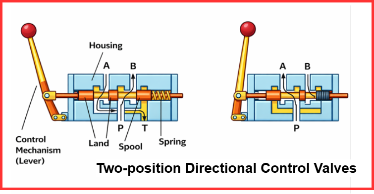
In the normal (non-actuated) condition, the spring holds the spool in its default position, creating the flow paths P to B and A to T. When the lever is operated, the spool shifts to the second position, reversing the connections to P to A and B to T, which changes the direction of fluid flow.
Applications
- Widely used in basic hydraulic circuits due to their simple operation and reliable performance.
- Hydraulic cylinder control – ideal for applications where the cylinder needs to fully extend or fully retract.
- Hydraulic motor control – suitable for motors that operate only in forward or reverse direction.
- Provide an efficient solution for simple actuator control in spool valve hydraulic systems.
Three-position Directional Control Valves
A three-position valve functions similarly to a two-position valve but includes an additional center (neutral) position, providing greater operational flexibility.
Three-position valves have three distinct spool positions, allowing improved control over fluid direction and system performance. The center position plays a crucial role, as its configuration determines how the fluid behaves when the valve is idle—flow may be blocked completely or partially allowed depending on the spool design.
Characteristics:
- Neutral (center) position for idle or standby operation
- Enhanced system control compared to two-position valves
- Reduced energy losses during idle conditions
- Versatile configuration options based on spool design
This design makes three-position valves ideal for applications requiring more precise control of actuators and hydraulic circuits.
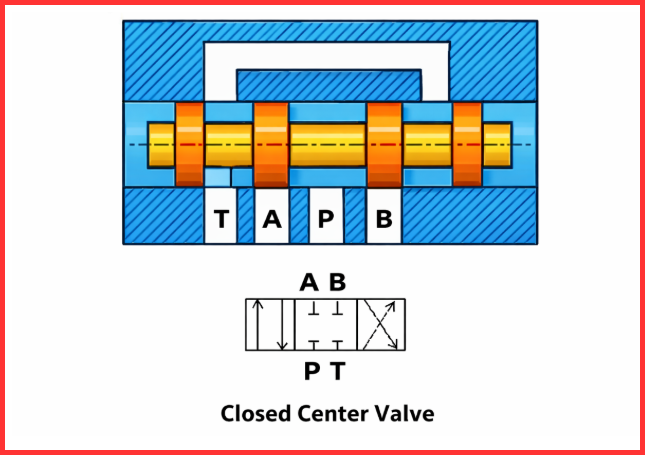
Closed Center Valve
In a closed center valve, all ports are blocked in the neutral position, preventing any fluid flow between them when the valve is idle. This configuration ensures that actuators remain securely held in position, even while the pump continues to supply fluid to other parts of the system, such as charging an accumulator or operating additional actuators.
Advantages:
- Maintains system pressure during idle conditions
- Ideal for load-holding applications
- Suitable for high-pressure hydraulic systems
- Provides precise and reliable actuator control
Applications:
- Hydraulic presses where consistent force is required
- Precision control systems in industrial machinery
- Mobile equipment requiring actuator locking under pressure
The closed center design is widely used in variable displacement pump systems and load-sensing circuits, offering both efficiency and secure control of hydraulic actuators.
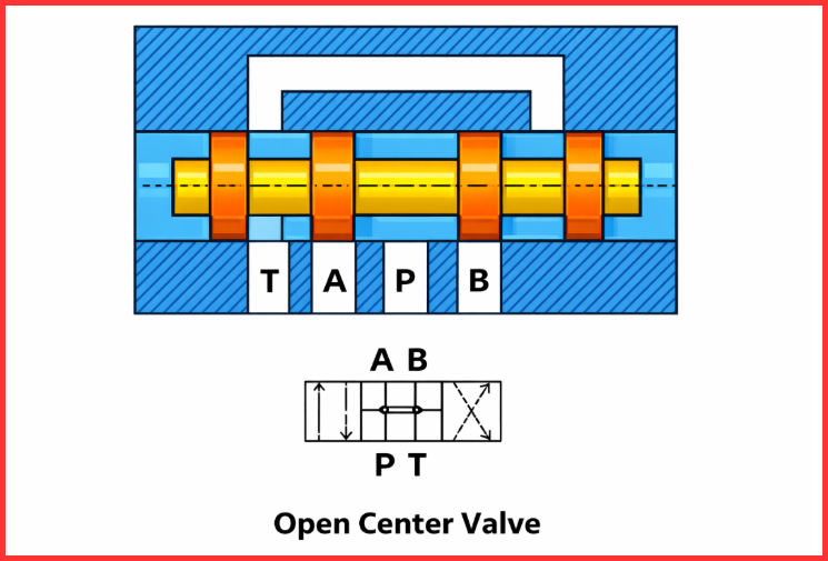
Open Center Valve
An open center valve allows all ports to remain connected in the neutral (center) position, enabling fluid to flow freely back to the tank when the valve is not actuated. In this configuration, the valve cannot support the actuator against gravity or lock it at a specific position.
Advantages:
- Reduced heat generation due to continuous fluid circulation
- Energy-efficient, as the pump does not build unnecessary pressure when idle
- Simple circuit design, making it easy to integrate into hydraulic systems
Applications:
- Agricultural machinery such as tractors and harvesters
- Mobile hydraulic systems in construction and material handling equipment
- Suitable for controlling rotary actuators in both forward and reverse directions
The open center design is widely preferred in hydraulic systems with fixed displacement pumps, providing reliable performance and efficient operation in applications where free-flowing fluid is acceptable when the system is idle.
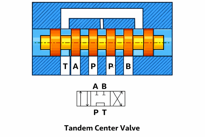
Tandem Center Valve
A tandem center valve connects the pump (P) and tank (T) ports, allowing the hydraulic pump’s discharge to return freely to the tank. At the same time, the spool in the neutral position blocks the actuator ports (A and B), maintaining pressure on both sides of the actuator to hold it in place.
Advantages:
- Protects the pump by preventing unnecessary pressure buildup
- Maintains actuator position, ensuring stability during idle conditions
- Energy-efficient operation by allowing free flow from pump to tank
Applications:
- Industrial hydraulic systems requiring precise load holding
- Multi-valve circuits where actuators need to remain stationary while other functions operate
This configuration is ideal for systems that demand actuator stability and pump protection simultaneously.
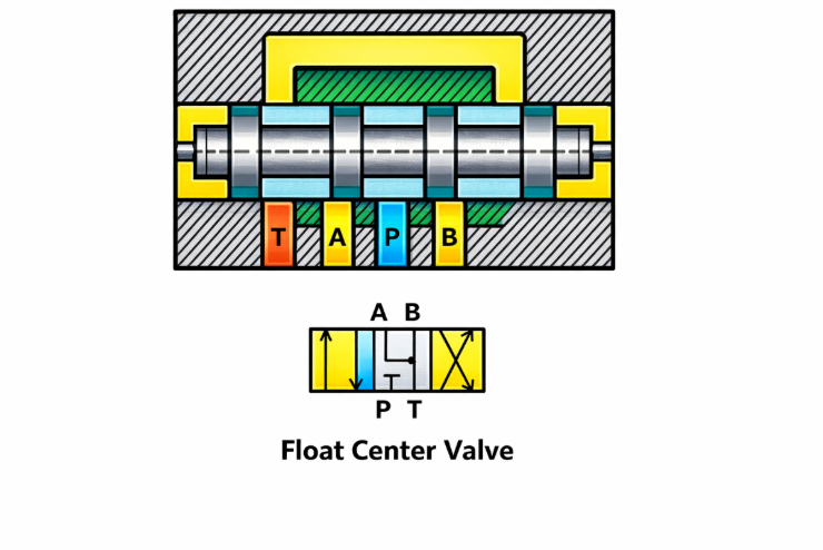
Float Center Valve
A float center valve connects both actuator ports (A and B) to the tank in the neutral position, allowing hydraulic fluid to flow freely back to the tank. At the same time, the pump port (P) is blocked from the tank, preventing pump flow from being wasted and ensuring efficient system operation.
Advantages:
- Allows free movement of actuators, enabling them to “float” under external forces
- Prevents pressure buildup in the system during idle conditions
- Protects the pump and enhances overall hydraulic efficiency
Applications:
- Hydraulic motors requiring smooth bidirectional operation
- Loader arms and mobile equipment where actuators need to move freely without resistance
- Ideal for variable displacement pump systems and mobile hydraulic applications
Applications of Spool Type Valve
Spool valves are used across multiple industries, including:
- Hydraulic power units
- Industrial automation
- Oil and gas plants
- Mobile equipment
- Construction machinery
- Hydraulic motor control (motor spool systems)
Their versatility makes them one of the most widely used spool valve types in fluid power engineering.
Conclusion
Understanding the types of spool valve is essential for selecting the right valve for any hydraulic or pneumatic application. From rotary and sliding designs to various center configurations, spool valves provide precise control, flexibility, and reliability. Whether used in simple circuits or complex hydraulic spool valves systems, the spool type valve remains a fundamental component in modern fluid control technology.
Read Next: