Zero Elevation and Zero Suppression are two important calibration concepts used in level measurement systems, especially in differential pressure (DP) transmitters. These techniques help engineers accurately measure liquid levels when the transmitter is not installed at the same height as the tank reference point. Without proper zero adjustment, level readings can be misleading and unsafe for process control.
In this article, you will learn what zero elevation and zero suppression are, why they are required, how they work, key differences, practical examples, and real-world applications.
What Is Zero Elevation in Level Measurement?
Zero elevation is applied in level measurement when the transmitter senses pressure even at zero tank level. This situation typically arises when the transmitter is installed below the tank tapping point, where the liquid column in the impulse line creates a constant static head on the measurement system. As a result, the transmitter detects positive pressure even though no liquid is present in the tank.
In a zero-elevated configuration, the zero reference is shifted upward during calibration so that the transmitter output correctly represents the actual level. The output signal is adjusted to compensate for the static head pressure, ensuring that only the true liquid level contributes to the measurement.
Zero elevation is most commonly used in open tanks where transmitters are mounted below the process connection. However, careful installation is essential. If the liquid level drops below the transmitter elevation and a proper seal system is not used, the DP transmitter may become unstable due to air or gas entrainment, which can negatively impact accuracy.
Zero Elevation In a Wet Leg Installation
In a wet leg installation, the low-pressure side of the level transmitter is continuously subjected to a greater hydrostatic pressure than the high-pressure side. This occurs because the wet leg height (X) is intentionally maintained slightly higher than the maximum liquid level (H) inside the vessel.
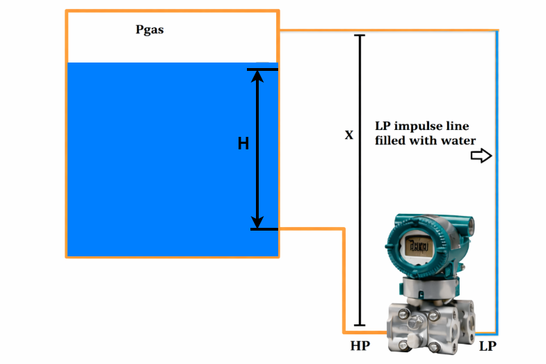
When the liquid level reaches H meters, the pressures acting on the transmitter can be expressed as:
- High-pressure side: Phigh=Pgas+S×H
- Low-pressure side: Plow=Pgas+S×X
The resulting differential pressure is:
ΔP=Phigh−Plow=S×H−S×X=−S(X−H)
Since X is always greater than H, the differential pressure remains negative, indicating that the pressure on the low-pressure side exceeds that on the high-pressure side under all operating conditions.
To achieve accurate level measurement, the transmitter must be calibrated by applying a positive offset equal to S × X. This adjustment shifts the output upward so that the measured signal correctly reflects the actual liquid level.
This method of applying a positive bias during calibration is known as Zero Elevation.
What Is Zero Suppression in Level Measurement?
When a transmitter is mounted below the vessel connection, the liquid column in the impulse line introduces additional pressure that affects the measurement range. In such situations, zero suppression is applied to reduce the transmitter output and compensate for this offset.
Zero suppression is also required when pressure exists at zero level, such as in closed or pressurized tanks, where constant vapor pressure or vacuum conditions act on the low-pressure side even when no liquid is present.
In a suppressed zero configuration, the zero reference is shifted downward, meaning the true zero of the measured variable lies below the transmitter’s lower range value. This adjustment helps eliminate false readings and ensures accurate level measurement under these conditions.
Zero Suppression When the Transmitter Is Mounted Below the Open Tank
In certain installations, a level transmitter must be positioned X meters below the bottom of an open tank. In this arrangement, the liquid trapped in the high-pressure impulse line creates a constant static head on the high-pressure side of the DP transmitter. This pressure can be expressed as P = S × X, where S represents the liquid specific gravity.
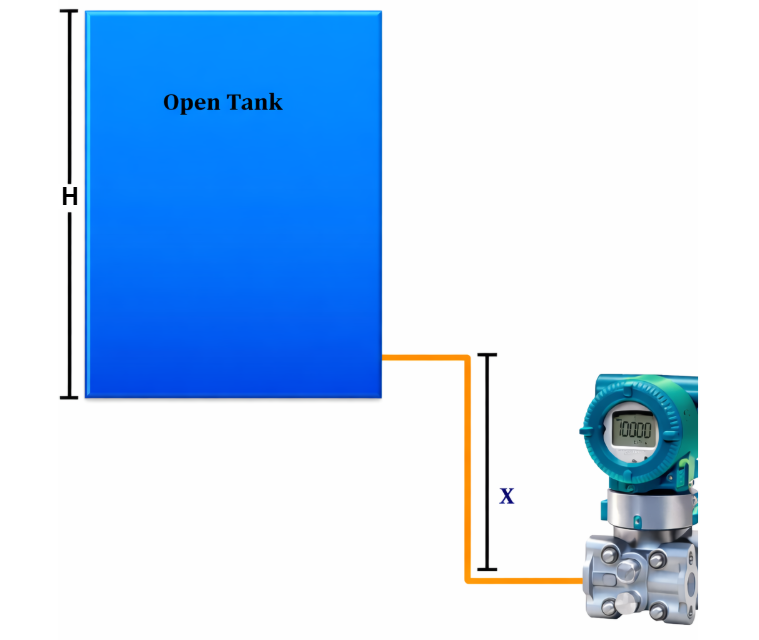
As a result, the pressure sensed on the high-pressure side is always greater than the actual pressure produced by the liquid level inside the tank by an amount equal to S × X. If left uncompensated, this additional pressure causes the transmitter to indicate a higher-than-actual level.
Because of this constant offset, the transmitter would produce an output greater than 4 mA when the tank is empty and may exceed 20 mA when the tank is full, leading to incorrect level measurement.
When the liquid level in the tank reaches H meters, the pressures acting on the transmitter are:
- High-pressure side: Phigh = S×H+S×X+Patm
- Low-pressure side: Plow = Patm
Therefore, the differential pressure becomes:
ΔP=Phigh−Plow=S×H+S×X
To ensure that the transmitter output represents only the actual tank level (S × H), the transmitter must be calibrated with a negative bias equal to S × X. This adjustment removes the effect of the constant static head in the impulse line.
This calibration method is known as Zero Suppression, and it is typically applied during transmitter setup to achieve accurate and reliable level measurement.
Why Zero Elevation and Zero Suppression Are Required
Accurate level measurement is critical for safety and efficiency. Zero Elevation and Zero Suppression ensure correct transmitter calibration in non-ideal installation conditions.
They are required to:
- Compensate for static head pressure
- Correct installation height errors
- Improve measurement accuracy
- Prevent overfilling or dry running
- Ensure reliable process control
Zero Elevation vs Zero Suppression (Comparison Table)
| Parameter | Zero Elevation | Zero Suppression |
| Pressure at zero level | Positive | Higher or constant |
| Zero adjustment | Shifted upward | Shifted downward |
| Typical tank | Open tank | Closed / pressurized tank |
| Installation position | Transmitter below tapping | Transmitter above reference |
| Main purpose | Compensate static head | Remove pressure offset |
Applications of Zero Elevation and Zero Suppression
These calibration methods are widely used in industries such as:
- Oil and gas
- Power plants
- Chemical processing
- Water and wastewater treatment
- Refineries and petrochemical plants
They are especially useful in:
- DP level transmitters
- Boiler drum level measurement
- Pressurized vessel monitoring
- Tall storage tanks
Common Mistakes to Avoid
- Ignoring transmitter mounting height
- Not calculating static head correctly
- Applying zero elevation instead of suppression (or vice versa)
- Skipping recalibration after system changes
Proper understanding avoids costly errors and inaccurate readings.
Conclusion
Zero Elevation and Zero Suppression play a vital role in accurate level measurement using DP transmitters. They compensate for installation constraints, static head pressure, and vessel conditions to ensure reliable readings. When applied correctly, these techniques improve safety, efficiency, and process control accuracy. Understanding the difference between zero elevation and zero suppression is essential for every instrumentation and control professional.
Read Next: