Wiring in a PLC control panel is a critical task that determines the reliability, safety, and performance of any industrial automation system. Proper wiring ensures accurate signal transmission, reduces electrical noise, simplifies troubleshooting, and improves long-term maintainability.
Designing wiring interlocks requires a thorough understanding of the intended control logic along with the applicable electrical standards. When an engineer clearly understands electrical wiring logic and interlock schemes, translating that logic into a PLC program becomes much simpler. In fact, strong expertise in hardwired control logic often makes PLC logic development more intuitive and effective.
This article explains the complete wiring concept of a PLC panel by covering all major components, from the main power entry to terminal boards.
Wiring in PLC
Wiring in PLC control panels involves systematic interconnection of power supplies, input/output (I/O) modules, protection devices, and field instruments. Each wire must be correctly sized, color-coded, ferruled, and routed to avoid electrical interference and voltage drops.
Good PLC wiring practices focus on:
- Electrical safety
- Noise immunity
- Ease of expansion
- Compliance with industrial standards
A well-wired PLC panel not only improves system accuracy but also minimizes downtime during faults or maintenance.
Refer to the image below. For better understanding, let us consider a basic PLC control panel that includes all essential electrical components.
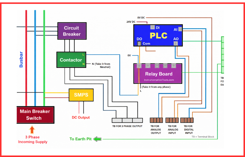
A typical PLC panel is equipped with a main incoming breaker, busbar system, circuit breakers, relays, contactors, PLC hardware, fuses, SMPS, terminal blocks, utility power sockets, and dedicated earthing points to ensure safe and reliable operation.
Components in PLC Control Panel & their Wiring
Main Breaker Switch
The main breaker switch is the primary power isolation point in a PLC control panel. It is where the incoming three-phase supply (R, Y, B, and Neutral) is connected and from which power is distributed to all panel components. The breaker enables complete panel isolation during maintenance or emergency conditions.
Key wiring considerations for the main breaker switch:
- Installed at the incoming section of the panel
- Rated for the panel voltage and fault current
- Connected upstream of all internal circuits
- Mounted to allow safe and convenient wiring access
- Clearly labeled for operator identification and safety
The main breaker provides the first level of electrical protection and ensures safe shutdown of the PLC control panel.
Busbar
In the next stage, the output of the main breaker is connected to the busbar system, which serves as a common distribution point for phase, neutral, and earth conductors. The busbar ensures organized and reliable power distribution across the PLC control panel.
When multiple devices require single-phase or three-phase supply, the busbar provides an efficient and structured method for distributing power. Positioned immediately after the main breaker, it feeds circuit breakers, SMPS units, and other panel devices with consistent voltage and adequate current capacity.
Using a busbar offers several advantages, including reduced wiring congestion, uniform voltage distribution, improved current handling, and a cleaner panel layout. In contrast, looping three-phase cables between components is poor practice and may cause overheating, loose connections, or damage to the wiring and the entire panel.
Circuit Breakers
Consider a PLC control panel with multiple circuit breakers. The three-phase supply is distributed from the busbar to the input terminals of each breaker. These circuit breakers (MCB/MCCB) protect individual circuits from overloads and short circuits, ensuring safe and controlled power distribution within the panel.
Each circuit breaker supplies power to a dedicated contactor through its output terminals, enabling precise three-phase load control. Since contactors operate through PLC-controlled control circuits, providing individual breakers for each power circuit improves electrical isolation, operational safety, and output reliability.
In PLC panels, separate breakers are commonly used for power circuits, control power, PLC supply, I/O modules, and auxiliary equipment. Proper breaker rating based on load current, clear labeling, and logical grouping make troubleshooting easier and help prevent damage to sensitive PLC components.
SMPS
Next, a suitable supply is taken from the busbar and connected to the Switched Mode Power Supply (SMPS) through a dedicated circuit breaker. The SMPS converts the incoming AC voltage into a regulated DC supply, typically 24 V DC, which is required for the PLC and associated field devices.
The DC output from the SMPS is distributed using terminal blocks or DC busbars, especially when multiple components or higher current ratings are involved. This approach ensures proper segregation and organized distribution of DC power to the PLC CPU, I/O modules, sensors, and transmitters. Proper earthing and adequate ventilation around the SMPS are essential to minimize electrical noise and maintain reliable operation.
Once the power distribution is complete, the next step is to focus on wiring the PLC input and output (I/O) modules.
Digital Inputs
Begin with the digital input (DI) wiring, which receives ON/OFF signals from field devices such as push buttons, limit switches, and proximity sensors. Depending on the sinking or sourcing configuration, connect either 24 V DC or 0 V DC to the PLC input common. For example, if the common is 24 V DC, route 0 V DC to the respective field devices via the terminal board. Each terminal block typically has two connection points—one for the DC supply and the other for the PLC digital input channel.
For reliable operation and protection, many panels use fused terminal blocks, which safeguard the digital inputs and field devices. Key wiring practices include using shielded cables in noisy environments, maintaining correct polarity, grouping common terminals properly, and clearly tagging all field signals. Proper DI wiring ensures accurate signal transmission and prevents false triggering.
Digital Outputs
Next, focus on the digital output (DO) wiring, which sends control signals from the PLC to field devices such as relays, solenoids, contactors, and lamps. The same sinking and sourcing principles as digital inputs apply when connecting DOs.
For example, if the DO common is 24 V DC, connect 0 V and the respective PLC digital outputs to each relay. Each relay typically has two terminals—one connected to 0 V and the other to the PLC output channel. The relay wiring depends on the required output type (DC or AC). For a 230 V AC load, connect the line wire to the relay common, the NO terminal to the contactor’s line input, and the neutral wire to the contactor’s neutral input, completing the circuit.
Proper DO wiring practices include using interposing relays for high-current loads, separating AC and DC output circuits, installing flyback diodes for inductive loads, and ensuring correct grounding. Following these guidelines protects PLC output modules and ensures reliable and safe operation of the connected field devices.
Analog Inputs and Outputs
Next, the analog inputs (AI) and analog outputs (AO) are routed directly through terminal boards to the PLC. These signals handle continuous values such as 4–20 mA or 0–10 V from transmitters, sensors, and control valves. Using fused terminal boards is recommended for added protection of both the PLC modules and connected analog devices.
Key analog wiring practices include using shielded twisted pair cables, grounding the shield at only one end, keeping analog cables away from high-power lines, and connecting signals to dedicated terminals. Following these rules ensures accurate measurement, reliable transmission, and precise control in industrial processes.
Analog inputs (AI) and analog outputs (AO) handle continuous signals such as 4–20 mA or 0–10 V for transmitters and control valves.
Terminal Boards
Terminal boards act as the interface between field wiring and PLC internal wiring, helping to organize wiring, simplify maintenance, and provide flexibility when connecting field equipment. They also allow organized cable termination, easy fault isolation, clear signal identification, and safe expansion of I/O points. Each terminal should be properly numbered and documented in the panel wiring diagram.
When designing a PLC control panel, keep the following key points in mind:
- Understand electrical ratings and standards before selecting components, such as contactors, to ensure safe and reliable operation.
- Fuses are often installed after the main breaker to protect the panel from faults in the incoming three-phase supply. Additionally, transformers may be used to step down voltages according to system requirements.
- Fuses are also recommended after the SMPS to safeguard the PLC and other sensitive field devices.
- For three-phase devices with earth connections, maintain separate power and instrument earthing. Mixing them can cause safety hazards and interference.
- Although not shown in this example, terminal boards for PLC digital outputs are commonly used, especially for devices like valves that require 24 V DC output wiring.
- PLC cabinets can be designed in many ways, but understanding the basic requirements, electrical wiring principles, and PLC wiring techniques is crucial for creating a safe, organized, and efficient control panel.
By following these guidelines, you can ensure a well-structured PLC panel that is safe, maintainable, and reliable.
Conclusion
Wiring in a PLC control panel is not just about connecting wires; it is about creating a safe, reliable, and noise-free automation system. From the main breaker switch and busbar to digital and analog I/O wiring, every component plays a vital role in overall panel performance. By following structured wiring practices and proper segregation, PLC panels become easier to operate, maintain, and expand, ensuring long-term operational efficiency.
Read Next: