A PSV P&ID (Pressure Safety Valves P&ID) is a vital engineering document that illustrates how pressure safety valves and pressure relief devices are connected within a process system. In process industries, a well-prepared PSV or PRV P&ID clearly defines overpressure protection philosophy, showing safety valve symbols, inlet and outlet connections, and discharge routing. Accurate representation of PSVs, PRVs, and relief valves in a P&ID is essential for plant safety, regulatory compliance, and smooth operations.
What is a Pressure Safety Valve (PSV)?
A Pressure Safety Valve (PSV), often referred to as a pressure relief valve in general discussions, is a mechanical device designed to automatically release excess pressure from equipment when the pressure exceeds a safe limit. In engineering drawings such as a pressure relief valve P&ID or PRV P&ID, the PSV is shown as a mandatory safety element connected to the protected system.
PSVs are commonly installed on:
- Pressure vessels
- Pipelines
- Heat exchangers
- Boilers and steam headers
Importance of PSV P&ID in Process Design
The PSV P&ID or P&ID PRV acts as the master reference document during:
- Process design and detailed engineering
- HAZOP and safety reviews
- Installation and commissioning
- Operation and maintenance
Any mistake in a PSV P&ID or relief valve P&ID can result in improper installation, unsafe operation, or non-compliance with statutory requirements.
PSV and PRV Symbols in P&ID
Relief Valve and Safety Valve Symbols
In a PSV P&ID or PRV P&ID, pressure safety valves are represented using standardized safety valve symbols as per ISA or ISO conventions. These symbols are often grouped under relief valve P&ID symbols and clearly distinguish safety devices from control valves or regulators.
Guidelines
- Use consistent safety valve symbol representation across all drawings
- Clearly differentiate:
- PSV
- PRV
- Pressure relief valve
- Avoid confusion with P&ID pressure regulator symbols
PSV Tagging and Identification in P&ID
Each valve shown in a Pressure Safety Valves P&ID or pressure relief valve P&ID must have a unique tag number.
Typical Tag Example
PSV-101A
Tagging rules apply equally to:
- PSV P&ID
- PRV P&ID
- Relief valve P&ID
The tag number must match datasheets, line lists, and relief valve sizing calculations.
PSV Location and Inlet Connection Guidelines
In a Pressure Safety Valves P&ID, the inlet connection must be shown directly on the protected equipment or pipeline.
Key Rules
- Inlet piping should be short and straight
- Avoid unnecessary fittings or restrictions
- If isolation valves are shown:
- They must be locked or car-sealed open
- This condition should be noted on the P&ID PSV
PSV Discharge Piping in P&ID
A PSV P&ID or relief valve P&ID must clearly show where the relieved fluid is discharged.
Common Discharge Routes
- Flare header
- Closed vent system
- Safe atmospheric location
Best Practices
- Clearly label discharge lines (e.g., To Flare)
- Use flow direction arrows
- Do not terminate discharge lines ambiguously
PSV with Rupture Disk Representation
When rupture disks are installed along with PSVs, the configuration must be clearly shown in the Pressure Safety Valves P&ID or pressure relief valve P&ID.
Guidelines
- Show rupture disk using a separate symbol
- Indicate whether it is upstream or downstream of the PSV
- Add notes for burst pressure or monitoring connections
Instrumentation and Regulators in PSV P&ID
Depending on design philosophy, the Pressure Safety Valves P&ID may also show:
- Pressure gauges near the PSV inlet
- Pressure transmitters
- Drain and vent connections
Care must be taken not to confuse safety devices with P&ID pressure regulator symbols, as regulators perform control functions and not overpressure protection.
Applicable Codes Referenced in PSV and PRV P&ID
Although calculations are not included, Pressure Safety Valves P&IDs often reference applicable standards such as:
- ASME Section VIII
- API 520 and API 521
- ISO 4126
These references apply equally to Pressure Safety Valves, PRV, and pressure relief valve P&ID documentation.
Multiple PSVs in a Single P&ID
When more than one safety valve protects the same equipment:
P&ID Guidelines
- Show each PSV separately with unique tags
- Clearly indicate parallel installation or switching arrangements
- Maintain clarity between multiple safety valve symbols
Do’s and Don’ts for PSV and Relief Valve P&ID
Do’s
- Use standard relief valve P&ID symbols
- Keep tagging consistent across PSV and PRV P&IDs
- Clearly show inlet and discharge routing
- Maintain consistency between Pressure Safety Valves PSV and datasheets
Don’ts
- Do not mix safety valve symbols with pressure regulator symbols
- Do not omit discharge destinations
- Do not overcrowd the Pressure Safety Valves P&ID with construction details
Pressure Safety Valve P&ID – Summary
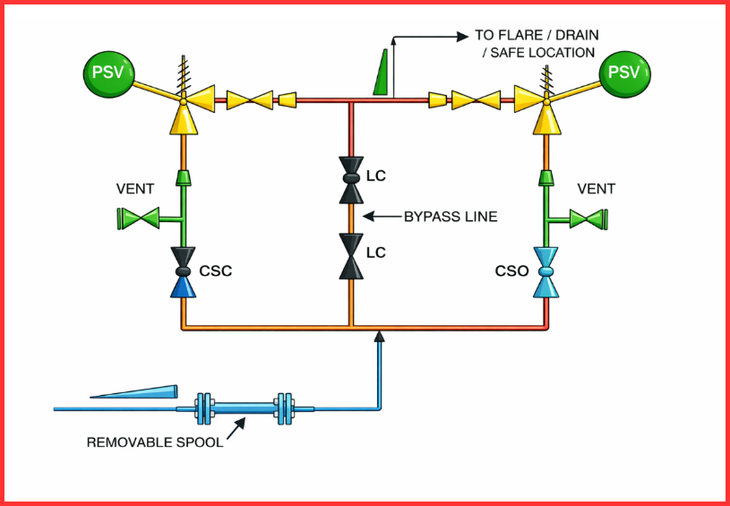
- A Pressure Safety Valve P&ID represents the standard arrangement of safety or relief valves used for overpressure protection in process systems.
- Correct safety valve symbols are selected as per project P&ID standards to clearly differentiate PSVs from control valves and pressure regulators.
- For critical equipment that cannot be isolated without plant shutdown, a spare pressure safety valve is typically provided and shown on the P&ID.
- Changes in inlet and outlet nozzle sizes are clearly indicated using reducers and expanders to reflect actual piping conditions.
- Block valves are provided upstream and downstream of the PSV for maintenance, with duty valve isolations shown as locked or car-sealed open.
- A vent valve is commonly installed between the upstream block valve and the PSV to allow safe depressurization during maintenance.
- Bypass lines may be included for start-up or process requirements, depending on project standards.
- PSV discharge routing is clearly shown, directing flow to a flare system, drain system, or a safe atmospheric location based on service conditions.
- Inlet piping is sloped toward the protected equipment, while outlet piping is sloped toward the flare header or safe discharge point.
- For PSVs connected to flare systems, an inlet spool piece is generally provided to simplify valve removal and maintenance.
- These Pressure Safety Valve P&ID practices are general guidelines and may be adapted to meet project-specific and code requirements.
Conclusion
A clear and well-structured PSV P&ID is essential for safe and compliant plant operation. By correctly applying relief valve P&ID symbols, safety valve symbols, proper tagging, and clear discharge routing, engineers ensure effective overpressure protection. Whether it is a Pressure Safety Valves P&ID, PRV P&ID, or pressure relief valve P&ID, following standardized guidelines helps improve safety, simplify reviews, and support reliable plant operation throughout its lifecycle.
Read Next: