MCR in PLC (Master Control Reset) is a powerful output-type ladder logic instruction used to enable or disable a defined block of program rungs based on a specific control condition. It allows the programmer to group multiple outputs and manage them together using a single logical requirement, instead of applying the same interlock repeatedly on individual rungs.
What is Mater Control Reset(MCR)?
MCR instructions are always used in pairs. The first MCR instruction defines the start of the MCR control zone, while the second MCR instruction marks the end of that zone. All ladder logic rungs placed between these two instructions belong to the MCR zone and are controlled as a single block.
In simple terms, when the MCR condition is true, all rungs inside the MCR zone are scanned and executed normally according to their individual logic. When the condition becomes false, the PLC automatically forces all non-retentive outputs within the MCR zone to a predefined safe state, typically OFF. This makes MCR especially useful for safety functions, mode selection, and emergency shutdown logic.
Using the MCR instruction, all related outputs can be disabled simultaneously when the controlling condition goes OFF. Typically, an input such as an emergency stop, safety interlock, or auto/manual selector is applied on the rung containing the first MCR instruction to control logic continuity.
When this rung goes false, every non-retentive output inside the MCR zone is de-energized. When it returns true, the PLC resumes normal scanning of all rungs within the zone. The closing MCR instruction does not require any condition; it simply defines the boundary of the controlled logic section.
Problem Logic
Consider an industrial process where multiple motors, valves, and indicators must operate only when the system is in AUTO mode and a Safety Permit is active.
If AUTO mode is turned OFF or the safety condition fails, all related outputs must stop immediately, regardless of individual rung conditions. Implementing this logic using separate interlocks on every rung makes the program lengthy and difficult to maintain.
This is where MCR in PLC becomes extremely useful.
Step Conditions:
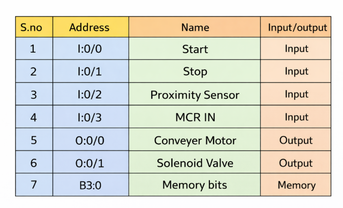
- Start and Stop Control: The process is initiated using the Start push button and halted using the Stop push button.
- MCR Activation: The MCR zone must be active for the process to start and execute correctly.
- Conveyor Operation: When the Start button is pressed, the conveyor begins moving and continues until the Proximity Sensor is triggered.
- Solenoid Valve Timing: Once the sensor is activated, the solenoid valve opens for 5 seconds. After the 5-second interval, the conveyor resumes movement.
- Batch Control: The sequence repeats automatically for 3 bottles in each cycle.
- Continuous Operation: The process continues to run until the Stop button is pressed.
- Emergency Override: In case of an emergency, if the MCR condition turns OFF, all outputs within the MCR zone are immediately disabled, regardless of individual input conditions.
List of Inputs and Outputs
MCR zones allow you to selectively enable or disable specific sections of a PLC program, making them ideal for applications like recipe control, subroutines, or grouped output management.
- When the MCR start rung is TRUE:
All rungs within the MCR zone operate normally, following their individual input conditions as if the MCR zone did not exist. - When the MCR start rung is FALSE:
All non-retentive outputs within the MCR zone are immediately reset, regardless of the logic or input conditions on individual rungs.
This behavior ensures that outputs in critical sections can be safely disabled in one step without modifying each rung separately.
PLC MCR Program
The PLC MCR program consists of:
- MCR Start Instruction – Defines the beginning of the MCR zone
- MCR End Instruction – Defines the end of the controlled zone
All rungs placed between these two instructions are controlled together.
If MCR Goes Off
When MCR goes OFF:
- All non-retentive outputs inside the MCR zone are forced OFF
- Timers inside the zone are reset
- Counters stop counting
- The PLC still scans the rungs, but output power flow is disabled
This behavior makes MCR in PLC ideal for emergency stop logic, mode selection, and safety grouping.
MCR Program Description
The following rung-by-rung explanation demonstrates how MCR is implemented in a typical PLC ladder program.
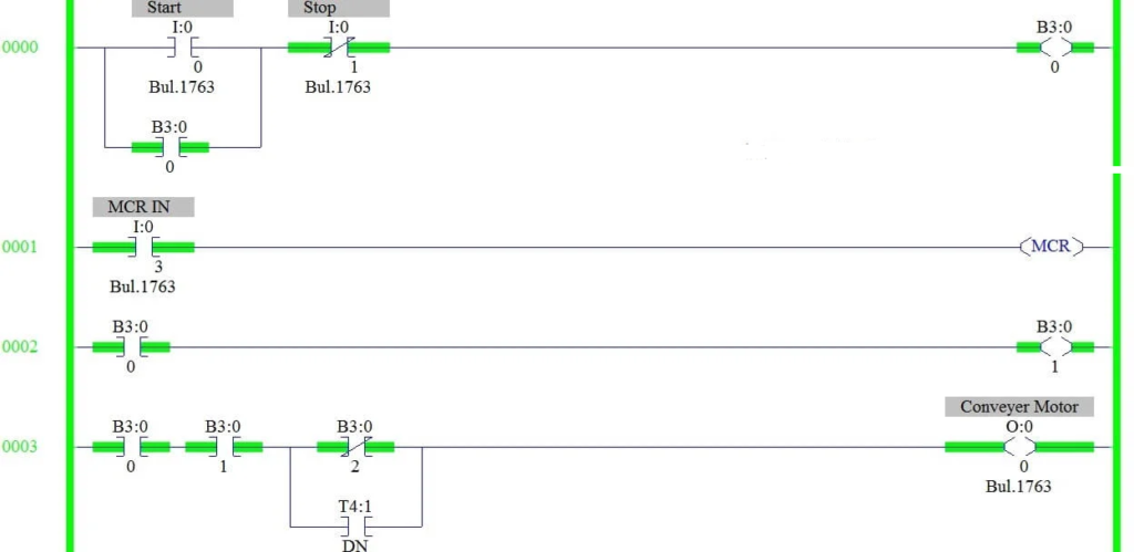
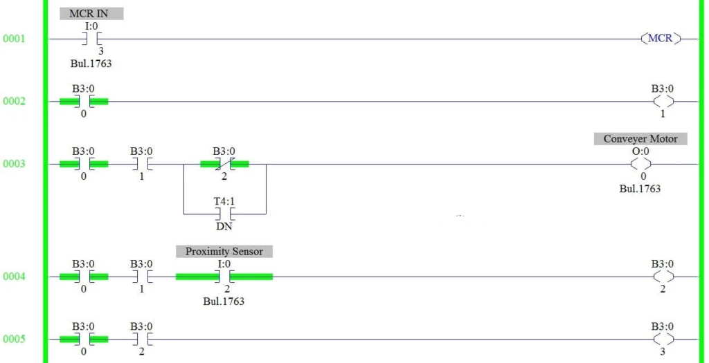
RUNG 0000
This rung creates a seal-in (latching) circuit that controls overall system operation using the Master Start and Stop push buttons.
RUNG 0001
An MCR (Master Control Relay) zone is initiated and enabled based on the assigned input condition.
RUNG 0002
The conveyor motor command is generated through an internal memory bit B3:0/1, which acts as a control flag.
RUNG 0003
The conveyor motor is energized using the latched start memory bit along with B3:0/1. When the proximity sensor triggers, B3:0/2 turns ON, causing the conveyor to stop automatically. Once the timer reaches the done state, it is connected in parallel to restart the conveyor motor.
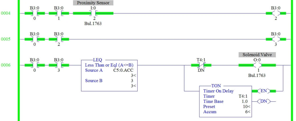
RUNG 0004
The output of the proximity sensor is stored in an internal memory bit for use in earlier logic conditions.
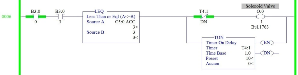
RUNG 0005 and RUNG 0006
The status of the proximity sensor is retained using memory bit B3:0/3. A comparator instruction checks the counter’s accumulated value and halts the process after three bottles are detected and filled.
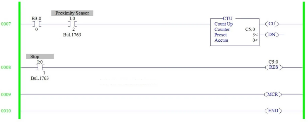
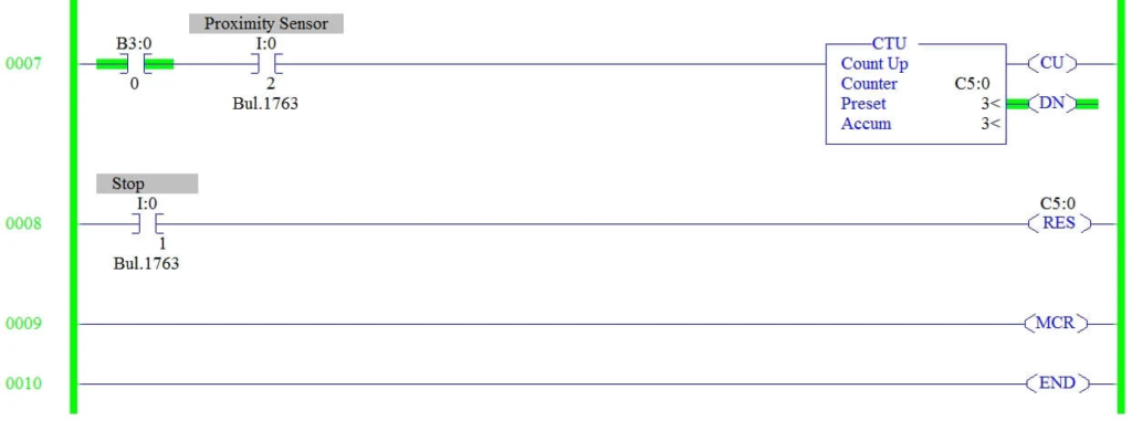
RUNG 0007
An up-counter increments each time the proximity sensor is activated. The preset value is configured to 3 to limit the process to three bottles.
RUNG 0008
The Stop push button input resets the counter and prepares the system for the next operation cycle.
RUNG 0009
The MCR zone is terminated at this rung, disabling all instructions within the controlled area when the MCR condition is false.
Conclusion
MCR in PLC is a simple yet highly effective instruction for controlling multiple outputs using a single condition. It improves program readability, reduces repetitive interlocks, and enhances system safety. By grouping related logic into an MCR zone, PLC programmers can quickly disable entire sections of a program during faults, manual mode, or emergency conditions.
When used correctly, MCR in PLC results in cleaner ladder logic, easier troubleshooting, and safer industrial automation systems.
Read Next: