When studying computer networks, one of the most fundamental structures you’ll encounter is bus topology. Understanding the advantages and disadvantages of bus topology is important because it helps in choosing the right network design for different situations.
In a bus topology, all devices are connected to a single central cable known as the backbone or “bus.” This cable acts as the main communication path, allowing data to travel across the network so that all connected devices can receive the signal.
In this article, we’ll explore how bus topology works, its applications, and how it compares to other network designs like star topology.
What is Bus Topology?
A bus topology in networking is a simple network structure where all devices are connected to a single central cable called the backbone. This cable acts as the main communication path, and data travels along it in both directions.
Whenever data is sent, it reaches all connected devices. Each device (node) checks the destination address (MAC or IP address). If the address matches, the device accepts and processes the data. If not, it simply ignores the signal.
This setup is also known as a bus network topology or bus topology, and it was widely used in early computer networks because of its simplicity and low cost.
Key Features of Bus Topology
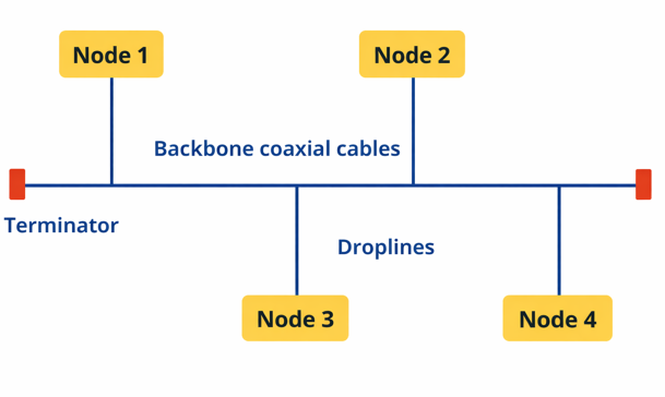
- A bus topology uses a single central cable (backbone) to connect all devices, creating a simple and efficient network structure.
- Devices (nodes) can either connect directly to the backbone or use drop lines (secondary cables) to join the network.
- It commonly uses the CSMA (Carrier Sense Multiple Access) method, where devices check if the network is free before sending data to avoid collisions.
- Terminators are installed at both ends of the backbone cable to prevent signal reflection and data loss.
- The performance of the network depends on the number of connected devices, as more nodes can lead to increased data traffic and slower communication.
How Data is Transmitted in Bus Topology
In a bus topology, all communication takes place through a single central cable known as the backbone or bus, which is shared by all connected devices. The data transmission process works as follows:
- Network Structure: All devices (nodes) are connected to one main cable, creating a shared communication path across the network. Terminators are placed at both ends of the cable to prevent signal reflection and ensure smooth data flow.
- Data Transmission: When a device sends data, the signal travels along the backbone in both directions and passes through the entire cable.
- Data Reception: Every connected device receives the signal, but each node checks the destination address. Only the intended device accepts and processes the data, while others ignore it.
- Collision Handling: Since all devices use the same communication line, simultaneous transmissions can cause collisions. To reduce this, protocols like CSMA/CD (Carrier Sense Multiple Access with Collision Detection) are used, where devices check if the line is free before sending data and detect collisions if they occur.
In a bus network topology, all devices share the same communication line. When a
Advantages of Bus Topology
Let’s explore the advantages bus topology offers:
- Simple to set up: A bus topology has a straightforward design, making it easy to install and use.
- Low cost: It uses less cable than other topologies, which helps reduce overall expenses.
- Works well for small networks: It performs efficiently when only a few devices are connected.
- Easy to expand: New devices can be added without making major changes to the network.
- Flexible device management: Devices can be connected or removed without affecting others.
- Easy to understand: Its simple structure makes it beginner-friendly and requires less technical knowledge.
- Less hardware required: Since it doesn’t need a central hub or switch, maintenance is simpler.
Disadvantages of Bus Topology
Despite its simplicity, bus topology comes with several drawbacks:
- Single Point of Failure
If the main backbone cable is damaged, the entire network stops working, or it may break into separate segments. - Limited Cable Length
The backbone cable has a maximum length, which restricts network size. - Performance Degradation
As more devices are added, network speed decreases and performance drops, making it unsuitable for large networks. - Difficult Troubleshooting
Identifying faults or issues in the main cable or individual devices can be challenging. - Need for Terminators
Terminators must be installed at both ends of the main cable to ensure proper network functioning. - Data Collisions
When multiple devices send data at the same time, collisions can occur, increasing the chance of data loss. - Slower Compared to Other Topologies
Overall, bus networks generally offer slower performance than alternatives like star or mesh topologies.
Advantages and Disadvantages of a Bus Topology (Quick Summary)
This table below gives a quick overview of the advantages and disadvantages of a bus topology.
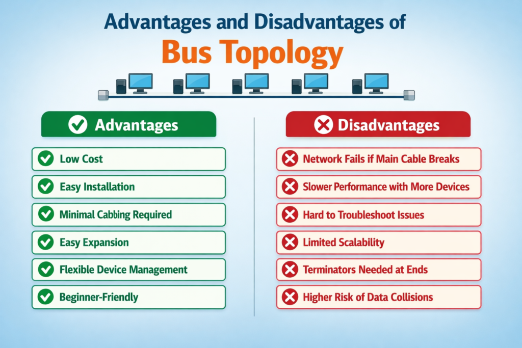
| Advantages | Disadvantages |
| Low cost | Entire network fails if the main cable breaks (single point of failure) |
| Easy installation | Slower performance as more devices are added |
| Minimal cabling required | Difficult to troubleshoot faults in cable or devices |
| Easy expansion | Limited scalability due to backbone cable length |
| Flexible device management | Terminators required at both ends of the main cable |
| Beginner-friendly / easy to understand | Higher chance of data collisions |
Bus Topology Applications
Bus topology is best suited for simple, cost-effective networks that require minimal cabling. While less common in modern high-traffic networks, it continues to be used in specific scenarios:
- Small Networks (SOHO) – Ideal for small offices or home environments where only a few devices need to be connected, minimizing cost and complexity.
- Local Area Networks (LANs) – Traditionally used in early Ethernet LANs, connecting computers via daisy-chained coaxial cables in legacy setups.
- Industrial Control Systems – Commonly implemented in factories and industrial automation, linking sensors, actuators, and other devices in distributed control systems, including PROFIBUS and CAN bus networks.
- Instrumentation and Laboratory Networks – Suitable for connecting meters, sensors, and data acquisition equipment in lab or commercial environments.
- Building Automation and HVAC Systems – Employed to integrate thermostats, actuators, sensors, and other control devices along a shared communication line.
- Temporary or Short-Term Networking – Useful for events, exhibitions, or temporary workstations due to ease of setup and flexibility.
- Education and Training – Frequently used in classrooms and labs to demonstrate basic networking principles, physical layer behavior, and simple topologies.
- Telecommunications (Legacy Systems) – Historically applied in early telephone networks and data transmission systems, though modern telecom relies on more advanced topologies like mesh or ring for better scalability and fault tolerance.
Best Practices for Bus Topology Design
- Plan for Growth – Design the network to handle additional devices without slowing down performance.
- Use Quality Cabling – Choose well-shielded coaxial cables with appropriate bandwidth to reduce interference and signal loss.
- Terminate Properly – Place a 50-ohm terminator at both ends of the backbone to prevent signal reflection and data corruption.
- Keep a Linear Layout – Maintain a straight backbone line, connecting devices with short drop lines to preserve signal integrity.
- Minimize Drop Line Lengths – Short cables between the backbone and devices reduce attenuation and maintain reliable communication.
- Avoid Overloading – Limit the number of devices per segment to prevent congestion and performance drops.
- Add Redundancy When Possible – Consider backup segments to reduce the risk of a single point of failure.
- Use Segments or Bridges to Expand – For larger networks, divide into multiple segments connected with bridges or repeaters for better performance and manageability.
Types of Cables Used in Bus Topology
Bus topology primarily relies on a single backbone cable that connects all devices in the network. While coaxial cables are the traditional choice, twisted-pair (Cat5/Cat6) and RJ-45 cables can also be used depending on the setup.
Key cabling points:
- Backbone Cable – The main line connecting all devices in the network.
- Drop Cable – Short cables linking individual devices to the backbone.
- Terminators – Required at both ends to prevent signal bounce and data corruption.
- Cable Choice – Coaxial is traditional and reliable; twisted-pair is flexible and easier to integrate with modern hardware; fiber optics can be used for specialized or hybrid setups.
Using the right cables ensures stable signal transmission, minimizes collisions, and maintains network reliability. Classic bus networks favor coaxial cables, while modern implementations often use twisted-pair cables for greater flexibility and ease of integration.
Connecting Multiple Bus Topologies
Multiple bus topologies can be linked together, but careful planning is needed to maintain network reliability and performance. Common methods include:
- Cascading Buses – Connect buses end-to-end in a linear sequence, so the end of one bus becomes the start of the next. This allows devices across different segments to communicate while keeping a simple linear structure.
- Using Repeaters or Signal Amplifiers – Repeaters or amplifiers can extend the length of the backbone by regenerating signals, allowing multiple bus segments to connect over long distances without data loss or degradation.
- Segmenting with Hubs – Network hubs or switches can link separate bus segments. While this introduces a partial centralization, it effectively integrates multiple buses into a unified network.
- Hybrid Topologies – Bus networks can be combined with other topologies, such as star or tree structures, to create hybrid designs. For example, a star-bus topology connects several bus segments through a central hub, combining the benefits of both layouts.
Comparison: Bus Topology vs Star Topology
Understanding bus topology is easier when compared with star topology, a common alternative network design.
Advantages of Star Topology
- Dedicated Connections: Each device connects directly to a central hub, providing consistent performance.
- Fault Isolation: A failure in one device or cable does not affect the rest of the network.
- Centralized Control: Easier network management and monitoring through the hub.
- Scalability: New devices can be added without disrupting the existing network.
- Improved Reliability: Centralized design reduces the risk of total network failure.
Key Differences Between Bus and Star Topology
| Feature | Bus Topology | Star Topology |
| Cost | Low – uses minimal cabling and no central hub | Higher – requires a hub/switch and more cabling |
| Reliability | Low – single backbone failure affects the entire network | High – only the affected node or cable is impacted |
| Performance | Degrades as more devices are added | Stable – each device has a dedicated connection |
| Installation | Simple – linear backbone with drop lines | Moderate – requires central hub and individual connections |
| Failure Impact | Entire network may go down if backbone fails | Only the affected device or cable is impacted |
When to Use Bus Topology?
Bus topology works well in situations where simplicity and cost savings are priorities:
- Small Networks: Ideal for home networks or small office setups with only a few devices.
- Temporary Installations: Suitable for short-term networks, such as labs, events, or testing environments.
- Budget-Friendly Projects: Requires minimal cabling and no central hub, making it a cost-effective choice.
Note: For larger or modern networks, star topology is usually preferred because it offers higher reliability, better performance, and easier fault management.
Conclusion
The advantages and disadvantages of bus topology make it a simple yet limited networking option. While it is cost-effective and easy to implement, its lack of scalability and reliability makes it less suitable for large or modern networks.
If you’re building a small network, bus topology can still be a practical choice. But for long-term and scalable solutions, alternatives like star topology are more efficient.
Read Next: