Stilling Wells for Level Measurement are vertical pipes or chambers installed inside tanks, vessels, and reservoirs to provide a relatively calm area for measuring liquid levels. They reduce the influence of turbulence, splashing, waves, and disturbances caused by pumps or agitators, helping level instruments produce more stable readings.
A stilling well is commonly used with float-type level sensors, displacer instruments, ultrasonic level transmitters, and radar level measurement systems. It is particularly useful when the liquid surface fluctuates or when equipment inside a vessel creates continuous movement.
The performance of a stilling well depends on its diameter, length, material, mounting arrangement, and the type of level instrument installed. Proper design is essential to ensure that the liquid level inside the pipe represents the actual level in the tank.
What Is a Stilling Well?
A stilling well is a vertical, usually cylindrical pipe installed in a liquid-containing vessel to isolate the level measurement area from external disturbances. Openings or connections allow the liquid level inside the well to follow the level in the surrounding vessel.
The pipe reduces rapid fluctuations in the local liquid surface, allowing the measuring element to operate under more stable conditions. Depending on the instrument and process, the stilling well may be open at the top, closed at the top, or designed with specific connections and equalization holes.
Stilling wells are commonly used in storage tanks, process vessels, hydraulic oil reservoirs, water tanks, and industrial liquid measurement systems.
Working Principle of a Stilling Well
The working principle of a stilling well is based on reducing turbulence around the level-sensing element while allowing the liquid level to equalize with the surrounding liquid.
The process works as follows:
- Installation: A vertical pipe is installed at a suitable location inside the tank or vessel, with the level sensor positioned inside or associated with it.
- Liquid entry: The liquid enters the stilling well through its open end, side openings, or other designed connections.
- Disturbance reduction: The pipe shields the sensing region from direct splashing, strong currents, and surface waves.
- Level equalization: The liquid level inside the well adjusts to the surrounding level through the available openings or connections.
- Measurement: The level instrument measures the liquid level under more stable conditions.
The stilling well does not eliminate all liquid movement. Instead, it reduces local disturbances that can interfere with measurement.
For accurate measurement, the well must allow sufficient hydraulic communication with the tank. If the openings become blocked or the well is poorly designed, the internal level may lag behind or differ from the actual tank level.
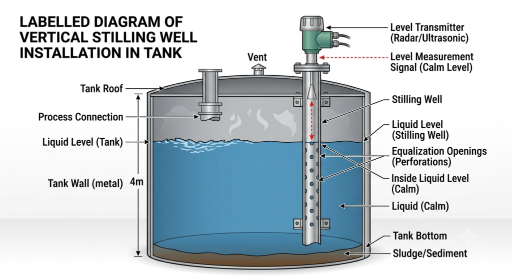
Stilling Well Diagram and Construction
A typical stilling well consists of a vertical pipe, suitable mounting supports, a level-sensing instrument, and openings that allow the liquid to communicate with the surrounding vessel.
The main components are:
- Vertical pipe: Forms the protective chamber around the sensing area.
- Level instrument: Measures the liquid level inside or along the well.
- Equalization holes or slots: Allow liquid to move between the vessel and the well when required by the design.
- Mounting supports: Hold the pipe securely in position.
- Top and bottom arrangements: Provide the required access, venting, drainage, or process connections, depending on the application.
The exact construction varies with the instrument type. A radar stilling well, for example, must have suitable internal geometry and surface conditions for the radar signal, whereas a well used for a float or displacer must provide adequate mechanical clearance.
Why Are Stilling Wells Used in Level Measurement?
Stilling wells are used when liquid movement causes unstable or unreliable readings. Their main purpose is to provide a more controlled measurement zone without necessarily changing the operating conditions of the entire vessel.
1. Reduction of Turbulence
Liquid entering a tank through an inlet nozzle can produce strong currents and splashing. A stilling well helps protect the sensing element from these disturbances.
2. Stable Level Indication
Surface waves and rapid level fluctuations can cause a transmitter’s output to fluctuate. A properly designed stilling well reduces these local variations and can provide a more stable indication.
3. Improved Radar Measurement
Radar level instruments can experience unwanted reflections from internal structures, agitators, or turbulent surfaces. A compatible stilling well can provide a more controlled path for the radar signal, subject to the manufacturer’s installation requirements.
4. Protection of Mechanical Sensors
Float and displacer instruments can move excessively when exposed to strong currents or waves. A stilling well can reduce this unwanted movement and help maintain consistent operation.
5. Measurement in Confined or Disturbed Areas
A stilling well can provide a dedicated measurement zone where unrestricted installation of a sensor in the main vessel is impractical.
Types of Level Instruments Used with Stilling Wells
Stilling wells can be used with several level measurement technologies. However, compatibility depends on the instrument design and process conditions.
1. Float-Type Level Measurement
A float rises and falls with the liquid surface. A stilling well reduces the effect of waves and currents on the float, helping prevent excessive movement and unstable readings.
The pipe diameter must provide adequate clearance for the float to move freely throughout the measurement range.
2. Displacer-Type Level Measurement
A displacer instrument determines level from changes in buoyancy acting on a suspended displacer. A stilling well can protect the displacer from direct liquid currents and reduce unwanted movement.
The well must not restrict the displacer’s movement or create excessive friction and contact with the pipe wall.
3. Radar Level Transmitters
Radar transmitters measure the distance to the liquid surface using electromagnetic waves. In suitable applications, a stilling well provides a controlled measurement path and can help reduce interference from surface disturbances.
The pipe’s internal diameter, straightness, material, joints, and surface condition must meet the radar manufacturer’s requirements. A conventional pipe cannot automatically be assumed suitable for every radar instrument.
4. Guided Wave Radar Level Transmitters
Guided wave radar uses electromagnetic pulses guided along a probe. A coaxial probe or specially designed chamber can help measure liquids in confined spaces and can be useful for liquid-liquid interface measurement.
Equalization openings may be necessary so that the interface inside the chamber follows the interface outside it. Their number, position, and size must follow the instrument design and process requirements.
5. Ultrasonic Level Transmitters
Ultrasonic instruments measure the distance to the liquid surface using sound waves. A stilling well may be suitable for certain applications, but reflections from the pipe wall, internal condensation, foam, and installation geometry can affect performance.
The arrangement should be approved by the instrument manufacturer rather than selected solely to reduce turbulence.
Practical Example of a Stilling Well in a Hydraulic Oil Reservoir
Consider a hydraulic oil reservoir in which the oil level must be measured continuously using a displacer-type level instrument. During operation, oil entering and leaving the reservoir creates currents and surface disturbances. These movements can cause the displacer to fluctuate, resulting in unstable level readings.
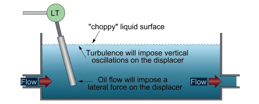
To reduce this problem, a vertical pipe can be installed around the displacer. The pipe acts as a protective chamber, reducing the direct influence of incoming oil currents and surface waves on the sensing element.
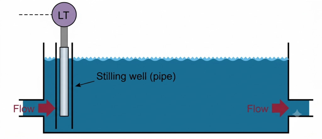
As the oil level changes, oil moves into or out of the stilling well through its designed openings. The level inside the chamber can therefore follow the reservoir level while remaining less affected by local turbulence. This arrangement helps the displacer operate more steadily and improves the consistency of the measurement.
The same principle can be applied to other compatible instruments, including float-type sensors, radar level transmitters, ultrasonic sensors, and certain laser-based level measurement systems. The suitability of a stilling well depends on the instrument design and the operating conditions.
Practical Example of Stilling Wells for Liquid-Liquid Interface Measurement
A stilling well can also be used to measure the interface between two immiscible liquids, such as oil and water. In this application, the instrument must detect the boundary between the two liquid layers rather than only the upper liquid surface.
A critical design requirement is that the interface inside the well must correspond to the actual interface in the vessel.
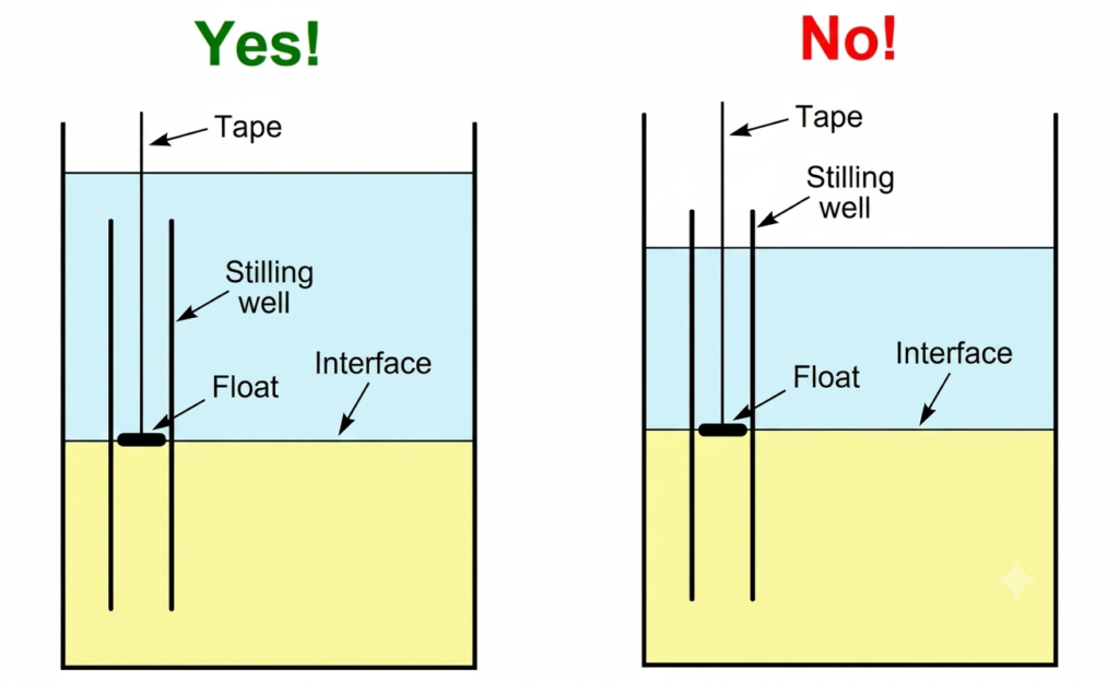
For accurate measurement, the interface inside the stilling well must correspond to the interface in the main vessel. The chamber’s installation and liquid communication arrangements are therefore important.
When a stilling well is completely submerged in a suitable liquid system, the interface can equalize with the surrounding vessel, provided the chamber allows adequate communication between the two regions. However, if the top of the well extends above the total liquid level, the interface inside the chamber may not always match the actual interface outside it.
This difference can lead to incorrect interface readings, particularly when the chamber does not provide the required hydraulic communication.
How Equalization Holes Improve Interface Measurement
If complete submersion is not practical, properly designed holes or slots may be provided in the stilling well. These openings allow the liquids to communicate between the chamber and the main vessel, helping the internal interface follow changes in the actual interface level.
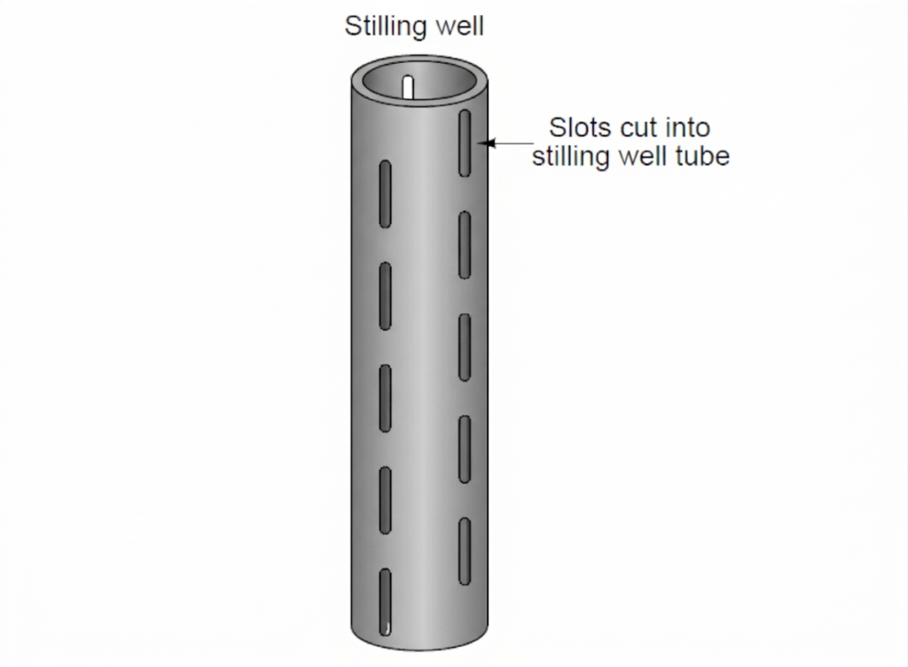
The openings must be positioned and sized according to the liquid properties, operating conditions, and instrument requirements. Incorrectly designed openings can cause delayed response, blockage, or measurement errors.
A similar arrangement is used in certain coaxial guided wave radar probes. The outer tube helps guide the radar signal and can provide a more controlled measurement environment. Equalization openings may be incorporated to allow the liquid levels and interface inside the probe to correspond to those outside it.
These features are particularly important when measuring oil-water interfaces, where reliable detection depends on both the radar probe design and the correct equalization of the liquid layers.
Stilling Well Pipe Size and Dimensions
The stilling well pipe size is an important design consideration because it affects liquid movement, sensor clearance, response time, and measurement reliability.
There is no single pipe diameter suitable for all stilling wells. The required dimensions depend on the level instrument, measuring range, liquid properties, vessel geometry, and process conditions.
Important design parameters include:
| Design parameter | Purpose |
| Internal pipe diameter | Provides adequate clearance for the sensor and the required measurement path |
| Pipe length | Covers the required measuring range and installation elevation |
| Wall thickness | Provides the required mechanical strength and pressure capability |
| Equalization hole size | Allows sufficient liquid communication between the vessel and the well |
| Hole spacing | Supports level equalization across the measurement range |
| Material of construction | Provides compatibility with the liquid, temperature, and pressure |
| Straightness and alignment | Helps prevent sensor contact and measurement errors |
How to Select the Stilling Well Diameter
The internal diameter should be selected according to the instrument manufacturer’s recommendations. It must be large enough to accommodate the sensor, its movement where applicable, and the required signal path.
For radar measurement, the diameter must also be compatible with the antenna or probe design and the expected signal reflections. For float or displacer instruments, sufficient mechanical clearance is essential.
A larger diameter may provide more clearance but can allow greater internal liquid movement. A smaller diameter may restrict sensor movement or affect the instrument’s signal. Therefore, pipe size should not be chosen using diameter alone.
Stilling Well Pipe Size Chart
The following table is a preliminary reference for common nominal pipe sizes. These are illustrative nominal sizes, not a universal sizing recommendation for level measurement.
| Nominal pipe size (NPS) | Nominal size (DN) | Typical consideration |
| 1 inch | DN 25 | Only for instruments specifically designed for a small bore |
| 1.5 inches | DN 40 | May suit compact probes or specialized installations |
| 2 inches | DN 50 | Common starting point for evaluating some radar applications |
| 3 inches | DN 80 | Provides greater internal clearance |
| 4 inches | DN 100 | May suit larger probes or selected process applications |
| 6 inches | DN 150 | Considered where instrument geometry or process requirements demand a larger bore |
Important: The actual internal diameter depends on the pipe schedule and wall thickness. The appropriate size must be confirmed against the instrument manual, process design, and applicable engineering requirements. These nominal sizes should not be treated as a mandatory standard or a substitute for manufacturer approval.
Stilling Well Design Considerations
A properly designed stilling well must provide stable measurement without introducing excessive lag, blockage, or instrument interference.
1. Material Selection
The material must withstand the liquid’s chemical properties, operating temperature, and pressure. Stainless steel is used in many industrial applications, while carbon steel, coated steel, and suitable non-metallic materials may be appropriate for other services.
Material selection should consider corrosion, erosion, contamination, and any process-specific requirements.
2. Pipe Length
The well must cover the required measuring range and be installed at the correct elevation. The sensor’s reference point and the tank’s minimum and maximum operating levels must be considered during design.
3. Equalization Openings
Openings may be required to allow the liquid level inside the well to follow the tank level. Their size and location must balance adequate equalization with disturbance reduction.
Openings that are too small may become blocked or cause excessive response delay. Poorly positioned openings can create misleading readings, particularly when liquid layers or interfaces are being measured.
4. Internal Surface Condition
For radar applications, internal welds, protrusions, sharp edges, and misaligned pipe sections can produce unwanted reflections. The internal surface and joint arrangement should comply with the transmitter manufacturer’s specifications.
5. Mounting and Alignment
The pipe must be installed securely and kept sufficiently straight to avoid contact with a float, displacer, or probe. Vibration, thermal expansion, and mechanical loading should also be considered.
6. Venting and Drainage
The top and bottom arrangements must suit the application. A well may require venting, drainage, or specific pressure equalization provisions. These features must be engineered for the vessel’s pressure classification and process safety requirements.
Tips for Installation of Stilling Well in a Tank
The installation arrangement affects both the reliability and the response of the level measurement system.
The following practices should be considered:
- Install the well away from direct inlet jets, strong currents, and other sources of localized disturbance where practicable.
- Ensure the bottom and side openings provide suitable liquid communication.
- Check that the pipe does not interfere with agitators, internal baffles, heating coils, or other vessel equipment.
- Verify the sensor’s specified mounting distance, measuring range, and required clearance.
- Ensure the well is mechanically supported and aligned correctly.
- Confirm that the internal liquid level can follow changes in the main vessel.
- Inspect for obstructions, deposits, and trapped gas where these could affect measurement.
- Test the instrument across the expected operating range before placing the system into service.
For pressurized vessels, installation must also preserve pressure containment and comply with the approved vessel design. Any modification, drilling, or welding must be authorized and carried out under the applicable engineering and safety procedures.
Advantages of Stilling Wells
The main advantages of using a stilling well for level measurement include:
- Reduces the influence of local turbulence and surface waves.
- Helps stabilize readings from compatible level instruments.
- Shields floats and displacers from direct liquid currents.
- Can provide a controlled measurement path for suitable radar systems.
- May improve repeatability in vessels with disturbed liquid surfaces.
- Provides a defined location for installing or accessing certain level sensors.
Limitations of Stilling Wells
Although useful, stilling wells are not suitable for every application.
- Slower response: Restricted liquid exchange can cause the level inside the well to respond more slowly than the tank level.
- Blockage: Sediment, sludge, crystallization, or viscous deposits can obstruct the pipe or equalization openings.
- Measurement error: Poorly designed openings or unsuitable mounting can cause the internal level to differ from the actual level.
- Radar signal interference: Incorrect diameter, internal obstructions, or poor joints may create unwanted reflections.
- Maintenance requirements: The well may require periodic inspection and cleaning.
- Mechanical restrictions: A narrow pipe can interfere with a float, displacer, or probe.
The possibility of these limitations should be assessed before selecting a stilling well.
Stilling Well vs. Standpipe
The terms stilling well and standpipe are sometimes used interchangeably, but their meaning depends on the application.
| Feature | Stilling well | Standpipe |
| Main purpose | Reduces local liquid disturbances around a measuring point | Provides a vertical pipe or chamber for level indication or measurement |
| Typical application | Level transmitters and sensors in disturbed liquid | Level gauges, external chambers, or other level systems |
| Liquid communication | Designed to suit the instrument and process | Depends on the specific arrangement |
| Instrument compatibility | Requires attention to sensor geometry and signal requirements | Depends on the connected instrument and piping design |
| Design objective | Stable, representative level measurement | May provide level indication, instrument connection, or a measurement chamber |
A standpipe can function as a stilling well when it is specifically designed and installed for that purpose. The terminology alone does not establish whether the installation is suitable.
Maintenance and Troubleshooting
Periodic inspection helps maintain the accuracy and reliability of a stilling well installation.
Common problems and possible corrective actions are summarized below.
| Problem | Possible cause | Recommended action |
| Unstable level reading | Turbulence, vibration, or unsuitable installation | Check the mounting and instrument configuration |
| Slow level response | Restricted openings or excessive damping | Inspect openings and verify the design |
| Incorrect level indication | Blockage, poor equalization, or incorrect reference setting | Inspect the well and verify transmitter calibration |
| Float or displacer sticking | Deposits, insufficient clearance, or misalignment | Inspect and clean the chamber; check mechanical clearance |
| Radar measurement errors | Internal obstructions, unsuitable bore, or poor joints | Review the installation against the manufacturer’s requirements |
| Interface measurement errors | Incorrect chamber arrangement or blocked equalization ports | Verify the interface design and openings |
Inspection and maintenance must be performed using the approved isolation and safety procedures for the vessel. A pressurized or hazardous process chamber must not be opened until it has been made safe.
Applications of Stilling Wells
Stilling wells are used in a range of industrial and utility applications, including:
- Oil and hydraulic systems: To reduce the effect of circulating oil on level sensors in reservoirs.
- Water storage tanks: To reduce the influence of inlet turbulence on suitable level instruments.
- Chemical process vessels: To provide a controlled measurement zone where compatible with the chemical and process conditions.
- Fuel and liquid storage tanks: To support suitable radar or mechanical level measurement arrangements.
- Industrial process tanks: To reduce the influence of waves and agitation on selected instruments.
- Liquid-liquid interface systems: To provide a suitable chamber for measuring the boundary between immiscible liquids.
The final selection depends on the liquid properties, tank geometry, operating conditions, and the level measurement technology.
Conclusion
Stilling Wells for Level Measurement help reduce the effects of turbulence, splashing, and surface fluctuations around compatible level instruments. They are particularly useful in tanks and process vessels where disturbances can affect the stability of a level reading.
Reliable operation depends on selecting the correct pipe diameter, material, length, mounting arrangement, and equalization openings. The design must also account for instrument compatibility, response time, maintenance access, and process safety.
When properly engineered, a stilling well can improve measurement stability and repeatability. However, it should not be used as a universal solution for every level measurement problem; the installation must be suitable for the specific sensor and process conditions.
Read Next: