Magnehelic Gauge Calibration is the process of checking and verifying the accuracy of a differential pressure gauge by comparing its indicated readings with a known reference pressure. A digital manometer is commonly used as the reference instrument because it provides a precise pressure reading over the required measurement range.
A Magnehelic gauge is widely used to measure low differential pressures in HVAC systems, cleanrooms, air filters, ventilation ducts, and industrial processes. Regular calibration helps identify zero errors, pointer friction, hysteresis, and measurement deviations.
This article explains the working principle of a Magnehelic gauge, the equipment required, and the step-by-step calibration procedure using a digital manometer.
What Is a Magnehelic Gauge?
A Magnehelic gauge is a mechanical differential pressure indicator commonly associated with the Dwyer Magnehelic product range. It measures the pressure difference between two points and displays the result on an analog dial.
The gauge has two pressure connections:
- High-pressure port (H): Connected to the higher-pressure point or pressure source.
- Low-pressure port (L): Connected to the lower-pressure point or reference pressure.
The gauge measures the difference between these two pressures.
The differential pressure is calculated as:
Where:
- = Differential pressure
- = Pressure at the high-pressure port
- = Pressure at the low-pressure port
For example, if the high-pressure port receives 100 Pa and the low-pressure port receives 75 Pa, the indicated differential pressure should be:
Therefore, the gauge should indicate a differential pressure of 25 Pa, subject to its specified accuracy.
If the pressure at the low port exceeds the pressure at the high port, the differential pressure becomes negative. Whether the gauge can display a negative reading depends on its range and model.
Equipment Required for Magnehelic Gauge Calibration
Prepare the following equipment before starting the calibration:
- Digital manometer with a suitable measurement range and known accuracy.
- Low-pressure pneumatic hand pump or controlled pressure source.
- Flexible pressure tubing and suitable connectors.
- Tee fittings or a manifold, if required by the calibration arrangement.
- Reference pressure source or pressure controller, where applicable.
- Calibration record sheet for recording reference and gauge readings.
The digital manometer should have adequate resolution and accuracy for the gauge being calibrated. Check its calibration status before use.
Magnehelic Gauge Calibration Procedure
Follow the steps below to calibrate a Magnehelic gauge using a digital manometer.
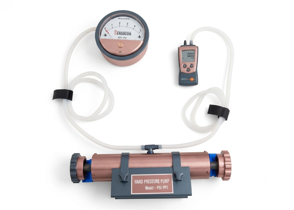
Step 1: Check the Gauge and Its Range
Inspect the gauge for physical damage, a cracked dial, loose connections, pointer obstruction, or other visible defects.
Record the following information:
- Instrument identification number
- Manufacturer and model
- Measuring range and units
- Gauge serial number, if available
- Calibration date
- Reference digital manometer identification
Verify that the gauge is suitable for the pressure range and that the pressure source will not exceed its specified operating limits.
Step 2: Position the Magnehelic Gauge Correctly
Install or hold the gauge in its specified operating orientation. Many Magnehelic gauges are designed for vertical mounting, so calibration should be performed in the manufacturer’s specified position.
An incorrect mounting orientation can affect the pointer’s zero position and measurement accuracy.
Allow the instrument to stabilize before beginning the calibration.
Step 3: Connect the Digital Manometer
Connect the digital manometer and pressure source using suitable tubing and fittings. Ensure that the connections are secure and leak-free.
For a gauge with a positive differential pressure range, a typical arrangement is:
- Connect the pressure source to the high-pressure port of the Magnehelic gauge.
- Connect the same pressure source to the digital manometer’s pressure input, using an appropriate tee or manifold.
- Keep the low-pressure port of the Magnehelic gauge at the same reference pressure as the digital manometer.
If the digital manometer measures differential pressure, connect its reference port according to its operating instructions.
This arrangement allows the digital manometer to provide the reference reading while the Magnehelic gauge displays the corresponding pressure.
Step 4: Check the Zero Reading
Before applying pressure, ensure that both ports of the Magnehelic gauge are exposed to the same pressure, normally atmospheric pressure for a gauge referenced to ambient.
The pointer should indicate zero differential pressure.
If the pointer does not return to zero, check for:
- Residual pressure in the tubing
- Blocked or incorrectly connected ports
- Leakage or trapped pressure
- Incorrect mounting orientation
- Mechanical pointer friction or instrument damage
Record the initial zero reading. Adjust the zero only if the manufacturer’s procedure permits it, and document any adjustment.
Step 5: Perform Preloading
Preloading helps check that the pointer moves freely and that the instrument has settled before formal readings are recorded.
Slowly increase the applied pressure toward the upper end of the measuring range, then reduce it back to zero. Do not exceed the gauge’s specified range or apply pressure beyond its permitted limits.
Observe the pointer for sticking, irregular movement, or failure to return to zero.
After preloading, allow the gauge and reference instrument to stabilize.
Step 6: Select the Calibration Points
For a gauge with a zero-to-full-scale range, five evenly distributed calibration points can be used:
| Calibration point | Applied pressure |
| 0% | 0% of full scale |
| 25% | 25% of full scale |
| 50% | 50% of full scale |
| 75% | 75% of full scale |
| 100% | 100% of full scale |
For example, if the gauge range is 0–1000 Pa, the calibration points are 0 Pa, 250 Pa, 500 Pa, 750 Pa, and 1000 Pa.
These are typical test points rather than a universal requirement. Use the points and acceptance criteria specified by the applicable procedure, manufacturer, or quality system.
Step 7: Perform the Up-Cycle Calibration
The up-cycle checks the gauge while the applied pressure increases from the minimum to the maximum calibration point.
- Set the pressure source to zero and verify the initial reading.
- Gradually increase the pressure until the first calibration point is reached.
- Allow the readings to stabilize.
- Record the digital manometer reading and the Magnehelic gauge reading.
- Increase the pressure to the next calibration point.
- Repeat the measurement and recording process at each remaining point.
- At the upper calibration point, confirm that the pressure remains within the permitted operating range.
Record the readings in the calibration table. Use the same pressure units for the reference and the gauge.
For consistent results, avoid overshooting the calibration point. If you exceed a setpoint, follow the approved procedure for approaching it again rather than assuming the reading is valid.
Step 8: Perform the Down-Cycle Calibration
The down-cycle checks the gauge while pressure decreases from the upper calibration point to zero.
- Begin at the highest calibration point reached during the up-cycle.
- Gradually reduce the applied pressure to the next calibration point.
- Allow the gauge and digital manometer readings to stabilize.
- Record both readings.
- Repeat the process at each remaining point until zero pressure is reached.
- Check whether the pointer returns to zero after the pressure is released.
Comparing the up-cycle and down-cycle readings helps identify hysteresis, which occurs when the gauge gives different indications at the same reference pressure depending on the direction of pressure change.
Step 9: Evaluate the Calibration Results
Compare each Magnehelic gauge reading with the corresponding digital manometer reading.
Calculate the error at each test point:
For a gauge with a zero-to-full-scale range, percentage of full-scale error can be calculated as:
For example, if the reference pressure is 500 Pa and the gauge indicates 520 Pa on a 0–1000 Pa gauge:
The gauge has a positive error of 20 Pa, equivalent to 2% of its full-scale range.
Compare the calculated errors with the instrument’s specified accuracy and the applicable acceptance limits. If the readings exceed the permitted limits, investigate the cause and adjust or repair the instrument only as authorized by the manufacturer’s procedure.
Step 10: Complete the Calibration Record
Record the as-found readings before making adjustments, where practical. If adjustment is performed, repeat the calibration and document the as-left readings.
The calibration report should include the instrument details, reference equipment, calibration points, up-cycle and down-cycle readings, calculated errors, adjustments, acceptance criteria, and final result.
Label the gauge according to the site’s calibration management procedure.
Magnehelic Gauge Calibration Observation Table
Use the following table to record calibration results.
| Applied point | Reference pressure | Gauge reading (up-cycle) | Gauge reading (down-cycle) | Error |
| 0% | ||||
| 25% | ||||
| 50% | ||||
| 75% | ||||
| 100% |
Enter the actual readings obtained during calibration. Calculate the error separately for each cycle when detailed results are required.
Important Precautions During Magnehelic Gauge Calibration
Observe the following precautions to obtain reliable results:
- Verify the calibration status and suitable range of the digital manometer.
- Keep the gauge in the manufacturer’s specified mounting orientation.
- Check tubing and fittings for leaks before taking readings.
- Ensure both ports are at equal pressure when checking zero.
- Apply pressure gradually to avoid pointer overshoot.
- Allow sufficient time for the reading to stabilize at each test point.
- Never exceed the specified pressure range of the gauge or reference instrument.
- Use the correct pressure units throughout the calibration.
- Record both increasing-pressure and decreasing-pressure readings.
- Follow the manufacturer’s instructions for zero adjustment and maintenance.
Common Problems During Magnehelic Gauge Calibration
| Problem | Possible cause | Recommended action |
| Pointer does not return to zero | Residual pressure, incorrect orientation, or mechanical friction | Equalize both ports and check mounting and instrument condition |
| Unstable pointer | Pressure fluctuations, leaks, or loose tubing | Check connections and stabilize the pressure source |
| High error at calibration points | Incorrect range, reference error, or gauge drift | Verify the reference instrument and inspect the gauge |
| Different up-cycle and down-cycle readings | Hysteresis or mechanical friction | Compare both cycles and inspect the instrument |
| Gauge does not respond | Blocked port, disconnected tubing, or internal damage | Check connections and follow the approved inspection procedure |
| Calibration result outside tolerance | Instrument drift, damage, or unsuitable calibration setup | Investigate, adjust or repair as permitted, and recalibrate |
Conclusion
Magnehelic Gauge Calibration using a digital manometer verifies whether the gauge measures differential pressure within its specified accuracy limits. The procedure involves checking the instrument’s condition and zero, connecting the reference equipment correctly, performing preloading, recording up-cycle and down-cycle readings, and calculating the measurement error.
A reliable calibration depends on the reference instrument’s accuracy, leak-free connections, correct mounting orientation, stable pressure application, and compliance with the manufacturer’s requirements. Documenting the results helps maintain dependable differential pressure measurement in HVAC and industrial applications.
Read Next: