Orifice plates are among the most widely used primary flow-measuring devices in process industries. Installed between two pipe flanges, they offer a simple, cost-effective, and reliable method for measuring flow rate. However, accurate measurement depends heavily on understanding orifice plate direction of flow, proper installation, and selecting the correct type of orifice plate for the application.
This article explains how do orifice plates work, the importance of orifice flow direction, and the different types of orifice plates used in industrial flow measurement.
How Do Orifice Plates Work?
An orifice plate works on the principle of differential pressure. When fluid flows through the restriction created by the orifice bore, the velocity increases and pressure decreases.
The point at which the fluid stream reaches its minimum cross-sectional area after passing through the orifice is called the vena-contracta. This is also the location of minimum pressure.
The pressure difference measured upstream and downstream of the orifice plate is directly related to the flow rate.
The flow behavior depends on the beta ratio (β), defined as:Where:
- d = orifice bore diameter
- D = inside pipe diameter
The beta ratio influences the location of the vena-contracta and the overall accuracy of the measurement.
Orifice Plate Flow Direction – Why It Matters
Understanding the orifice plate flow direction is critical because not all orifice plates are bidirectional.
- Some orifice plate types can be installed in either direction
- Others are strictly unidirectional and must face the correct upstream flow
Incorrect installation can lead to:
- Measurement errors
- Increased pressure loss
- Plate damage
- Flow instability
Manufacturers usually mark the upstream side on the orifice plate paddle to indicate the correct orifice plate direction of flow.
Square Edge Orifice Plate (Concentric Orifice)
The square edge orifice (also called a concentric orifice plate) is the simplest and most widely used design. It consists of a thin metal plate with a precisely machined circular hole at the center.
The square edge on an orifice plate is designed to reduce interaction between the plate and the high-velocity fluid passing through the opening. By maintaining a sharp, well-defined edge—ideally as sharp as a knife—the fluid separates cleanly from the plate surface, ensuring predictable flow behavior and accurate differential pressure measurement.
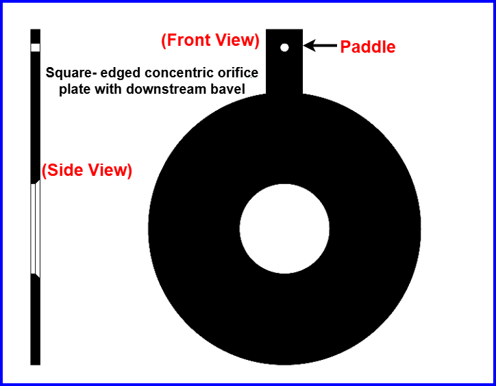
When an orifice plate has a relatively large thickness (typically 1/8 inch or more), the downstream edge of the bore is often beveled. This beveling helps reduce contact between the exiting fluid stream and the plate, allowing the flow to pass smoothly and minimizing turbulence, energy loss, and measurement errors.
Key Features:
- Sharp 90° upstream edge (knife-sharp ideally)
- Central bore
- Simple construction
- High repeatability
Orifice Flow Direction:
Square-edged orifice plates can be installed in either direction because they appear identical from both sides. This makes them suitable for bidirectional flow measurement, where flow may reverse.
Even though the paddle often carries an “INLET” marking, flow direction does not matter for a true square-edged concentric orifice.
Beveled Square-Edged Orifice Plate (Unidirectional)
When the orifice plate is relatively thick, the downstream edge of the bore is often beveled to reduce contact between the fluid and the plate.
Important:
- Sharp edge must face the incoming flow
- Bevel must be on the downstream side
- These plates are unidirectional
In this case, orifice plate direction of flow becomes critical, and the paddle text must face upstream.
Eccentric Orifice Plate
An eccentric orifice plate has an off-center bore to prevent buildup of unwanted materials.
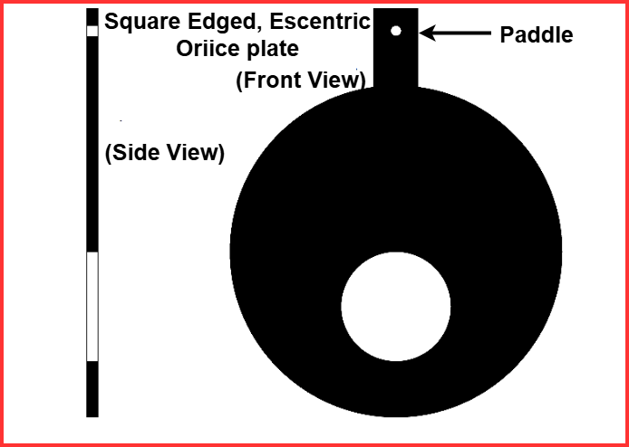
In gas flow applications, the orifice opening is positioned slightly downward so that any entrained liquid droplets or solid particles can pass through without accumulating. In liquid flow systems, the opening is offset upward to allow trapped gas bubbles to escape, while a downward offset is used when heavy solids are present, ensuring they move through the orifice instead of settling on the plate.
Application Guidelines:
- Gas flow: hole offset downward to allow liquid droplets to pass
- Liquid flow:
- Hole offset upward for gas bubbles
- Hole offset downward for heavy solids
This design minimizes measurement errors caused by trapped materials.
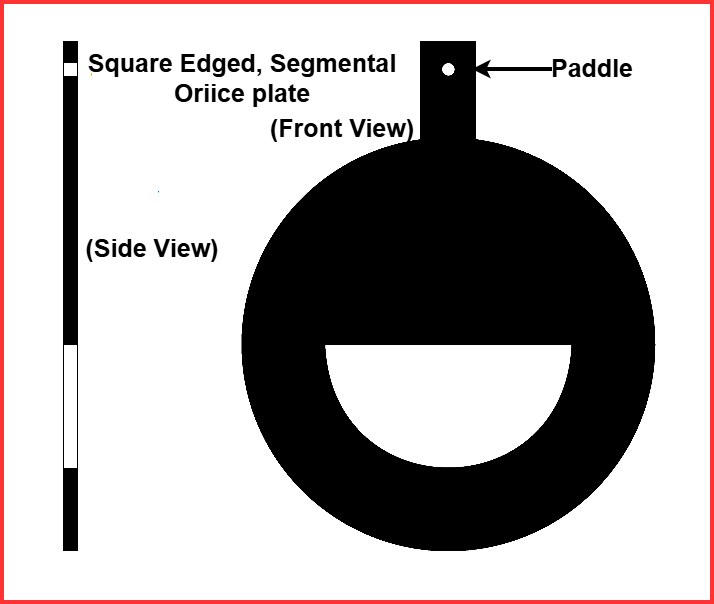
Segmental Orifice Plate
A segmental orifice plate uses a partial circular opening instead of a full bore.
Advantages:
- Better handling of slurries
- Reduced buildup of solids
- Suitable for dirty or multiphase fluids
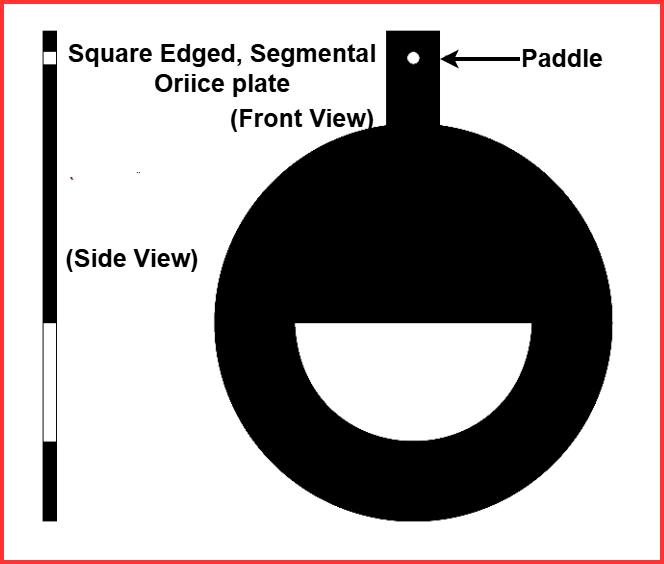
Similar to an eccentric orifice plate, a segmental orifice plate must be oriented correctly based on the process fluid. For gas flow applications, the segmental opening is positioned downward to allow liquids or solids to pass freely. In liquid flow systems, the opening may be placed either upward or downward, depending on whether gas bubbles or heavier solid particles are the primary unwanted materials in the flow stream.
Orifice Plate with Vent and Drain Holes
Instead of reshaping the bore, small auxiliary holes may be drilled near the pipe wall.
- Vent hole: placed at the top to release trapped gases
- Drain hole: placed at the bottom to discharge liquids or solids
These holes have negligible impact on flow accuracy and are ideal when contamination levels are low. For heavy contamination, eccentric or segmental plates are preferred.
Non-Square-Edge Orifice Plate Types (Low Reynolds Number Applications)
At low Reynolds numbers, viscosity effects reduce flow contraction, lowering differential pressure. To overcome this, special orifice plate types are used.
Quadrant-Edge Orifice Plate
This plate features a rounded inlet edge that improves performance at:
- Low flow rates
- High viscosity fluids
Conical-Entrance Orifice Plate
A conical-entrance orifice plate resembles a square-edge orifice plate with a beveled profile, but it is mounted in reverse orientation. In this arrangement, the process fluid first enters through the conical opening and then exits through the sharp, square-edged side, creating a controlled flow restriction.
The conical-entrance orifice plate has a tapered inlet that acts like a venturi.
Critical Installation Note:
- Flow must enter from the conical side
- Paddle marking is the only reliable indicator of correct installation
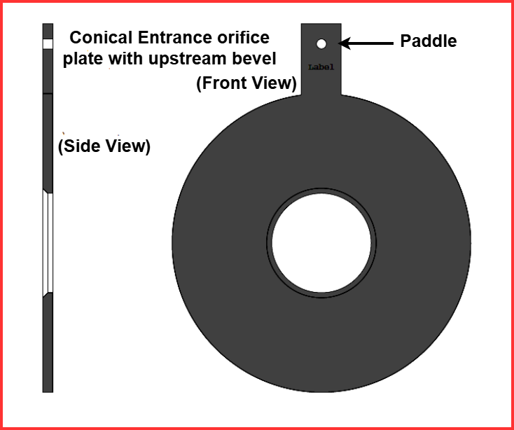
In this case, careful attention to the identification text stamped on the orifice plate paddle is absolutely critical. The marking clearly specifies the correct flow direction and is the only reliable guide for proper installation. Without checking this label, an instrument technician could easily confuse a conical-entrance orifice plate with a beveled square-edge plate and mistakenly install it in the reverse orientation.
Summary: Types of Orifice Plates
| Type of Orifice Plate | Description | Typical Applications |
| Concentric Orifice Plate | Circular bore located at the center of the plate | Clean liquids, gases, and steam flow measurement |
| Eccentric Orifice Plate | Off-center bore to prevent material buildup | Fluids containing suspended solids or gas pockets |
| Segmental Orifice Plate | Partial circular opening at the bottom of the plate | Slurries, dirty fluids, and viscous liquids |
| Quadrant-Edge Orifice Plate | Rounded inlet edge with quarter-circle profile | Low Reynolds number and viscous flow applications |
| Conical-Entrance Orifice Plate | Conical inlet and sharp-edged outlet | High-velocity flows with reduced pressure loss |
| Square-Edge Orifice Plate | Sharp, square-cut bore edge | Standard industrial flow measurement |
| Beveled Orifice Plate | Beveled downstream edge to reduce wear | High-velocity or erosive service conditions |
| Restrictor Orifice Plate | Designed mainly for pressure reduction | Pipeline pressure control and flow restriction |
| Integral Orifice Plate | Orifice integrated into a compact fitting | Small pipe sizes and packaged systems |
Summary: Choosing the Right Orifice Plate Type
Understanding types of orifice plates and correct orifice plate flow direction is essential for accurate flow measurement.
Quick Selection Guide:
- Clean fluids → Square edge orifice
- Bidirectional flow → Square edge orifice
- Gas with liquid droplets → Eccentric or segmental
- Slurries or dirty fluids → Segmental
- Low Reynolds number → Quadrant-edge or conical-entrance
Proper selection, correct orifice flow direction, and careful installation ensure reliable, repeatable, and accurate flow measurement.
Read Next: