In process control systems, the valve must open to the correct position to maintain flow, pressure, temperature, or level. However, friction, changing process pressure, and actuator limitations can cause the valve to deviate from the required position. Based on the control valve positioner working principle, a control valve positioner is used to correct this by adjusting the actuator air supply, ensuring the valve moves precisely to the desired position.
A Control Valve Positioner is a device that ensures the valve stem reaches the precise position as per the input control signal. It continuously adjusts the air pressure supplied to the actuator until the valve reaches the correct position.
What is the Function of a Control Valve Positioner?
The primary function of a valve positioner is:
- To compare the control signal (4–20mA or pneumatic signal) with the actual valve stem position.
- To increase or decrease air pressure to the actuator.
- To ensure the valve’s position is accurate, fast, and stable.
In simple terms: The positioner makes sure the valve goes exactly where the controller wants it to go.
Why is a Positioner Needed?
Positioners are used when:
| Condition | Reason |
| Accurate valve positioning required | Minimizes error and hysteresis |
| Large actuator travel distance | Ensures fast response |
| High friction or load in the valve | Helps overcome resistance |
| Long pneumatic tubing | Prevents slow/stuck movement |
| Control under varying process pressures | Maintains stability |
Control Valve Positioner Working Principle (Explained Step-by-Step)
The control valve positioner working principle is based on a force-balance mechanism between:
- The input signal (from the controller), and
- The feedback (actual valve position).
Step-by-Step Working:
- Controller Sends Signal
The process controller sends a pneumatic (3–15 psi) or electrical (4–20mA) signal to the positioner. - Positioner Compares Signals
The positioner compares the controller signal with the valve stem’s mechanical feedback. - Mismatch Detected
If the valve is not at the required position, the positioner adjusts actuator air pressure. - Air Pressure Adjusted
By opening or closing internal air ports, the positioner:- Adds air → Valve moves open
- Releases air → Valve moves closed
- Feedback Achieved
As the valve moves, the feedback linkage updates the positioner. - Equilibrium Reached
Once actual valve position = demanded position, the positioner stops adjusting air.
This continuous feedback loop ensures accurate control at all times.
Types of Control Valve Positioners
| Type | Description | Signal Type |
| Pneumatic Positioner | Uses air pressure for control | 3–15 psi |
| Electro-Pneumatic (EP) Positioner | Converts 4–20mA electrical signal to pneumatic pressure | Electrical + Air |
| Digital / Smart Positioner | Microprocessor-based with auto-tuning | 4–20mA + HART/Fieldbus/Profibus |
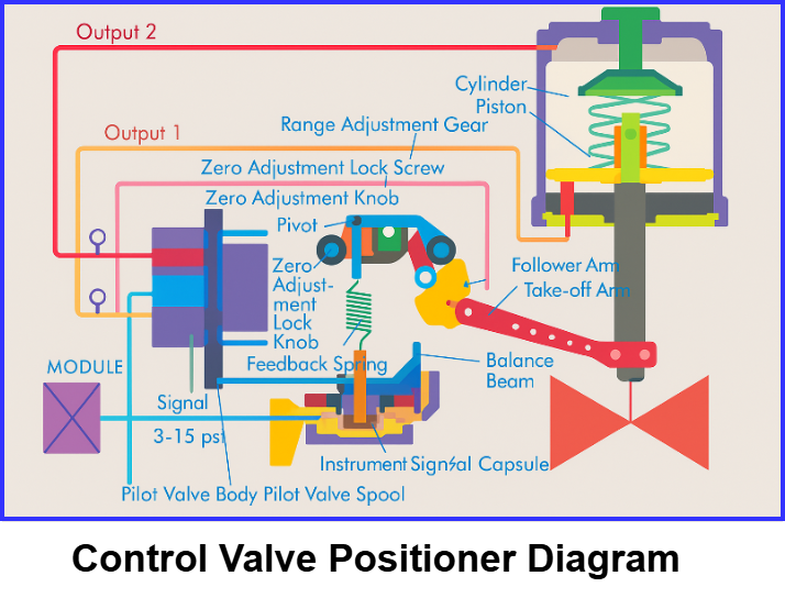
Control Valve Positioner Assembly
A control valve positioner assembly generally consists of a high-gain amplifier (which may be pneumatic, electro-pneumatic, or digital) and a mechanical feedback mechanism that continuously monitors the actual valve stem position. Together, these elements ensure that the valve moves precisely to the position demanded by the controller.
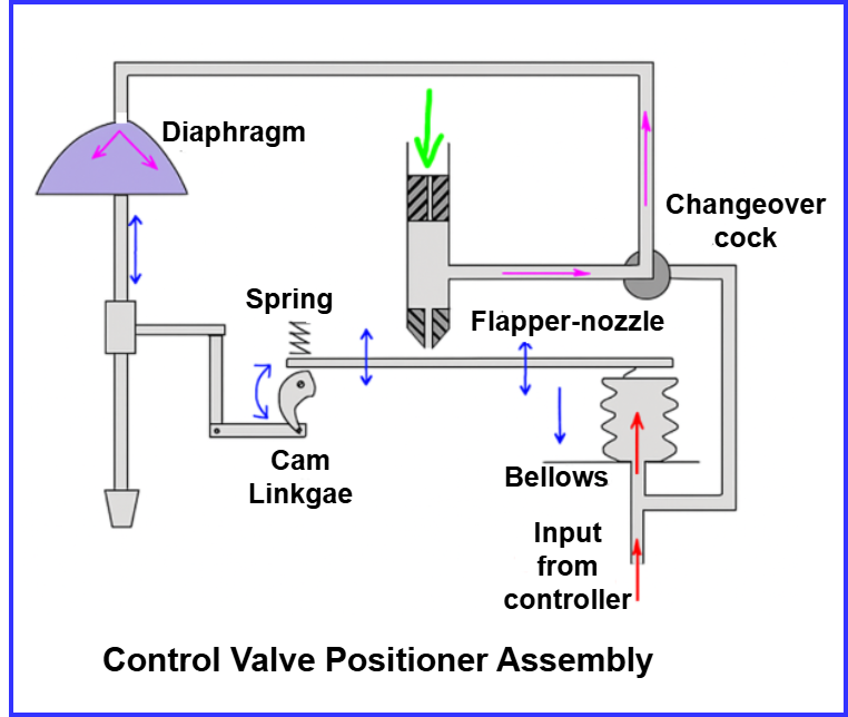
When the controller signal indicates that the valve should close, the input pressure to the bellows or diaphragm is reduced. As this signal pressure drops, the flapper shifts away from the nozzle, causing the nozzle back pressure to decrease. This reduction in back pressure results in a lower diaphragm pressure inside the actuator, causing the valve stem to move downward and initiate the closing action.
As the valve begins to close, the feedback arm attached to the valve stem also moves. This movement rotates the cam in a clockwise direction, which gradually increases the nozzle back pressure. This rise in pressure counterbalances the initial pressure change from the controller.
Eventually, a point is reached where the forces on both sides (signal force and feedback force) become equal, and the system returns to equilibrium. At this moment, the valve stops moving, holding a stable and accurate position.
Additionally, many positioner assemblies include a change-over cock. This feature allows the controller’s signal to be applied directly to the actuator diaphragm if required—effectively bypassing the positioner during maintenance or troubleshooting.
Control Valve Positioner Parts
A control valve positioner is made up of several mechanical and pneumatic components that work together to accurately control the movement of the valve stem. The main parts of a control valve positioner include:
1. Flapper–Nozzle Assembly
This is the core element responsible for converting small mechanical movements into pressure changes. When the flapper moves closer to or away from the nozzle, it changes the back pressure in the air supply line. This variation in pressure allows the positioner to precisely adjust the actuator’s movement.
2. Relay / Pilot Valve
The relay (or pilot valve) amplifies the small pressure signal generated by the flapper-nozzle assembly into a larger output pressure. It ensures sufficient air volume and pressure reach the actuator to move the valve quickly and control its position accurately.
3. Diaphragm or Bellows
The diaphragm or bellows receives the input control signal (either pneumatic or converted electrical). Its movement serves as the primary driving force that initiates the positioning action by reacting to changes in signal pressure.
4. Feedback Spring & Lever Linkage
This mechanism provides mechanical feedback of the actual valve stem position. As the valve moves, the feedback spring changes tension, allowing the positioner to continuously compare actual position with the desired setpoint and correct any positioning error.
5. Air Supply Ports
These ports deliver compressed air to the positioner and actuator, controlling airflow direction and pressure to ensure smooth valve movement.
6. Cam (Travel Characteristic Adjustment)
The cam defines how valve movement relates to input signal percentage. By changing cam profiles, you can achieve different control characteristics such as linear, equal percentage, or quick opening,.
7. Microprocessor (in Smart/Digital Positioners)
Digital positioners include an internal microprocessor that interprets electrical signals (4–20 mA), performs self-diagnostics, auto-calibration, and provides communication through protocols like HART, Fieldbus, or Profibus.
When Should a Control Valve Positioner Be Used?
A control valve positioner is not needed in every application, but it becomes essential when precise and stable valve movement is required. You should consider installing a valve positioner under the following operating conditions:
- When high positioning accuracy is required:
Positioners eliminate hysteresis and friction, ensuring the valve stem moves exactly to the demanded position. - To achieve faster valve response:
Since the positioner supplies higher pressure and air volume, it allows the valve to respond quickly to control signal changes. - To overcome higher closing or opening forces:
Positioners can act as pneumatic amplifiers, allowing the actuator to close or open against high differential pressures. - When experiencing high pressure drop across the valve:
If the pressure drop exceeds 5 bar in single-seated valves or 10 bar in double-seated valves, a positioner helps maintain stable operation. - To correct non-linear actuator characteristics:
Positioners help in linearizing the valve travel, improving process controllability. - Under fluctuating or varying process conditions:
When differential pressure changes, the positioner compensates automatically to maintain the correct plug position. - When the valve operates across a wide throttling range:
Positioners enhance control accuracy in applications requiring fine modulation across the entire valve stroke. - When handling viscous, slurry, or solids-laden fluids:
These media may cause stem sticking or drag; the positioner provides the power to overcome such resistance.
Control Valve Positioner Calibration (Basic Steps)
Calibration ensures that the valve positioner accurately aligns the valve stem position with the input control signal. Follow these steps to perform a basic calibration:
1. Ensure Correct Air Supply
Verify that the air supply pressure is within the manufacturer’s recommended range and that the air is clean and dry. Contaminated or insufficient air pressure can cause incorrect calibration and unstable valve movement.
2. Apply Zero Signal (4 mA or 3 psi)
Begin the calibration by applying the minimum input signal to the positioner.
- For electro-pneumatic positioners, this is typically 4 mA.
- For pneumatic positioners, it is usually 3 psi.
At this stage, the valve should be near the fully closed or starting position.
3. Adjust the Zero Screw
Use the zero adjustment screw to set the valve so that it just begins to move from its closed or initial position.
This ensures accurate response at the low end of the stroke.
4. Apply Full Signal (20 mA or 15 psi)
Next, apply the maximum input signal:
- 20 mA for electro-pneumatic systems
- 15 psi for pneumatic-only systems
The valve should now be close to its full open or maximum travel position.
5. Adjust the Span Screw
Use the span adjustment to correct the valve travel so that it reaches the full stroke limit correctly. This sets the relationship between the input signal range and the complete mechanical travel of the valve.
6. Verify Smooth and Repeatable Movement
Cycle the valve by applying intermediate values (e.g., 8 mA, 12 mA, 16 mA).
Check that:
- The valve moves smoothly without sticking or hesitation.
- The valve returns to the same position every time the same signal is applied.
If positioning is inconsistent, repeat fine adjustments to zero and span until motion is precise and repeatable.
Advantages of Using a Positioner
- High accuracy and repeatability
- Fast valve movement
- Eliminates friction and hysteresis effects
- Maintains performance under fluctuating process conditions
- Increases valve control range
Conclusion
The control valve positioner working principle ensures accurate valve operation by continuously adjusting air pressure to match the desired valve stem position. Without a positioner, control valves can become inaccurate, sluggish, or unstable due to friction and process disturbances. Therefore, in modern process control systems, positioners are essential for achieving high precision, fast response, and stable regulation.
Related Articles: