The Flow Meter K-factor is one of the most important parameters used in flow measurement and instrumentation systems. In simple terms, the Flow Meter K-factor defines the relationship between the output signal of a flow meter and the actual volume of fluid flowing through it.
Whether the flow meter generates pulse signals or analog signals, understanding and applying the correct K-factor is essential for accurate flow measurement, totalization, and process control in industrial applications.
What is Flow Meter K Factor?
The Flow Meter K-factor represents the number of output units—such as pulses, counts, or signal increments—generated per unit volume of fluid passing through a flow meter.
It acts as a calibration constant that converts the meter’s raw electrical output into meaningful engineering units such as liters, cubic meters, or gallons. Accurate use of the Flow Meter K-factor is essential for precise flow rate measurement and totalization in industrial applications.
K-factor formula of flow meter is;
K-factor = Number of output pulses / Unit volume of fluid
For example, if a flow meter produces 100 pulses per liter, then the K-factor is 100 pulses/L.
Key points about K-factors:
- It links flow meter output to real flow values
- It depends on meter type, size, and fluid properties
- It directly affects flow rate and total flow calculations
- An incorrect K-factor leads to inaccurate flow measurement
K-Factor Generation and Flow Calculation
The instrument delivers high accuracy and repeatability in Flow Meter K-factor generation by precisely detecting the rotation of a well-balanced turbine rotor.
As fluid flows through the meter, the rotor spins, and a magnetic pickup coil senses this motion, producing a frequency-based pulse signal. This pulse output forms the fundamental measurement principle of turbine-type flow meters. With proper factory or field calibration, measurement accuracy as high as ±0.15% can be achieved, making the system suitable for high-precision flow measurement.
Each pulse generated by the flow meter corresponds to a fixed and repeatable volume of fluid. The K-factor is determined by dividing the total number of pulses recorded by the actual volume of liquid that has passed through the meter. In simple terms, the Flow Meter K-factor defines how many pulses are produced for every unit volume of product flowing through the system.
In most flow meters—including turbine, positive displacement, and vortex flow meters—the K-factor is supplied by the manufacturer based on controlled factory calibration. However, under real process conditions, factors such as fluid viscosity, temperature, installation effects, and flow profile variations may influence measurement accuracy. In such cases, the K-factor can be adjusted through field calibration to achieve more accurate results.
Once the pulses are detected and counted, calculating flow rate and total volume becomes straightforward. Since the K-factor is expressed in pulses per unit volume, electronic systems such as PLCs, flow computers, and totalizers can directly display volumetric flow in standard engineering units without complex conversions.
Flow Rate Determination Using K-Factor
The pulse output frequency, defined as the number of pulses generated per unit time, is directly proportional to the rotational speed of the turbine rotor and therefore proportional to the flow rate. By dividing the pulse frequency by the Flow Meter K-factor, the instantaneous volumetric flow rate can be accurately calculated.
Standard electronic totalizers and flow computers continuously process these pulse signals to provide real-time flow rate indication, totalized volume, and multiple output options for monitoring and control. When the electrical output signal is plotted against flow rate, a calibration curve is obtained that defines the operating characteristics and performance profile of the turbine flow meter.
Although the Flow Meter K-factor concept is widely applied across many types of flow meters, it is important to note that in non-turbine meters the K-factor is often derived from analog measurement values rather than direct rotor sensing.
These systems rely on additional signal conversions—from analog values to frequency and sometimes back to analog for transmission—which introduce inherent uncertainties and may result in higher measurement error compared to direct pulse-based flow measurement systems.
Pulse Signal K-factors
All pulse-output flow meters are supplied by the manufacturer with a calibration certificate at the time of delivery. This document confirms that the meter has been tested and calibrated across its specified operating flow range under controlled conditions.
Pulse output flow meters generate electrical pulses as fluid passes through the sensing element, with each pulse representing a small and fixed volume of fluid. The calibration certificate includes the average K-factor, which defines the relationship between the pulse output and the actual volumetric flow through the meter.
The K-factor is expressed as the number of pulses produced per unit volume, for example 320 pulses per U.S. gallon or 180 pulses per liter. This form of K-factor expression makes pulse-based flow meters well suited for use with digital flow totalizers, PLC counters, and flow computers.
Because each pulse corresponds to a discrete volume, pulse-type flow meters are ideal for applications such as batching, dosing, and custody transfer, where accuracy and repeatability are critical. They also offer high measurement accuracy under steady flow conditions and provide excellent noise immunity, allowing reliable signal transmission over long distances.
The specified K-factor is programmed into a batch controller, flow indicator, or electronic totalizer. Once entered, the device converts incoming pulse signals directly into standard engineering units, enabling precise flow rate indication and total volume measurement with easy integration into digital control systems.
Calculations Using K-Factors
K-factor calculations are used to configure rate meters and totalizers so that flow readings are displayed in the desired engineering units. The value entered depends on the required time base and resolution of the display.
Example 1
Assume a flow meter has a K-factor of 250 pulses per U.S. gallon.
- If the rate meter is required to display flow in U.S. gallons per second, the K-factor entered into the rate meter will be 250.
- If a totalizer connected to the same flow meter is set to accumulate total flow in U.S. gallons, the totalizer K-factor will also be 250.
- If the totalizer is configured to totalize in tenths of a gallon, the effective K-factor must be scaled accordingly:
Totalizer K-factor=250/10=25
This allows the totalizer to increment once for every 0.1 gallon of fluid.
Example 2
If the same flow meter (250 pulses per U.S. gallon) is used with a rate meter that displays flow in U.S. gallons per minute, the K-factor must be adjusted for the time base:
Rate K-factor=250/60≈4.17
This adjusted K-factor ensures that the rate meter correctly converts pulse frequency into gallons per minute.
K-factors for Analog Input Signals
When batching, indication, or totalization is performed using an analog input signal, the flow meter output is typically a 4–20 mA current signal. Inside the receiving instrument or flow computer, this analog signal is first converted into a frequency signal, commonly in the range of 0 to 10,000 Hz.
The K-factor for analog inputs is calculated by relating the engineering unit value represented by 20 mA to the corresponding maximum frequency signal.
Example 3
Consider a vortex flow meter that outputs 20 mA at a flow rate of 3,000 U.S. gallons per minute. If the required rate display is in gallons per minute, the rate K-factor is calculated as:
Rate K-factor=10,000/3,000 ≈3.33
The totalizer K-factor depends on the time base of the flow rate and the desired totalization resolution.
- If the flow rate is expressed in units per second, the totalizer K-factor (for whole units) is: 3.33×1=3.33
- If the flow rate is expressed in units per minute, the totalizer K-factor (for whole units) is: 3.33×60≈200
If the flow rate is expressed in units per hour, the totalizer K-factor (for whole units) is:
3.33×3600≈12,000
To totalize in whole gallons, the totalizer K-factor is approximately 200.
If totalization in tenths of a gallon is required, the K-factor becomes:
(3.33×60)/10≈20
Example 4
An electromagnetic flow meter produces 20 mA at a flow rate of 30 liters per second. The flow rate must be displayed in liters per second, while total flow is required in cubic meters (m³).
The rate K-factor is calculated as:
Rate K-factor=10,000/30≈333.33
Since 1 cubic meter = 1,000 liters, the totalizer K-factor is:
333.33×(1/0.001)≈333,333
This K-factor ensures accurate conversion from instantaneous flow rate to totalized volume in cubic meters.
Key features:
- Used in analog input modules of PLCs and DCS
- Requires proper scaling in the control system
- Flow is calculated using linear interpolation
- Accuracy depends on correct range configuration
Unlike pulse signals, analog signals represent instantaneous flow rather than discrete volume increments.
Multi-Point K-factor
Certain flow measurement applications require the use of multiple K-factors to achieve accurate readings. This approach is necessary when a single K-factor cannot maintain sufficient accuracy across the entire flow range. Common scenarios include:
- Flow meters with non-linear outputs, where the meter’s response varies at different flow rates
- Applications with a wide turndown ratio, spanning very low to very high flow rates
- Situations where fluid viscosity changes or other process conditions fluctuate
- High-accuracy requirements at low flow rates
Many modern flow meters provide an option to enter between 3 and 16 K-factors, allowing the instrument to adjust its calibration dynamically across different flow points. Instead of relying on a single constant value, multiple K-factors are defined at specific flow rates, ensuring precise measurement across the full operating range.
This multi-point K-factor capability is available for both pulse-based and analog input signals, providing reliable and accurate flow measurement even under challenging process conditions.
Multi-Point K-factor for Pulse Inputs
Steps to Configure Multi-Point K-Factors
The process of setting up multi-point K-factors involves several key steps to ensure accurate flow measurement across the entire range:
- Determine K-factors for each flow segment
Begin by calculating K-factors for the different flow ranges. This can be done using the flow meter manufacturer’s calibration data or, alternatively, by performing on-site tests against a calibrated reference standard. - Associate frequency output with K-factors
Once the K-factors are determined, relate the flow meter’s incoming frequency or pulse output to each corresponding K-factor value for the specific flow points. - Program the instrument
Enter the calculated K-factor values into the flow computer, totalizer, or batch controller. The instrument will then automatically adjust its calibration based on the measured flow, ensuring accurate readings throughout the entire flow range.
Applying Multi-Point K-Factors in Pulse-Output Flow Meters
For pulse-output flow meters, multi-point K-factors are implemented by:
- Dividing the total flow range into multiple segments
- Assigning a unique K-factor to each segment
- Automatically switching between K-factors depending on the measured flow rate
This method enhances accuracy in critical applications such as chemical dosing, fuel measurement, and custody transfer systems. Modern flow computers and PLCs support multi-point K-factor tables, enabling advanced flow compensation and reliable measurement across varying process conditions.
Example 5
The following represents the calibration information for a turbine flow meter:
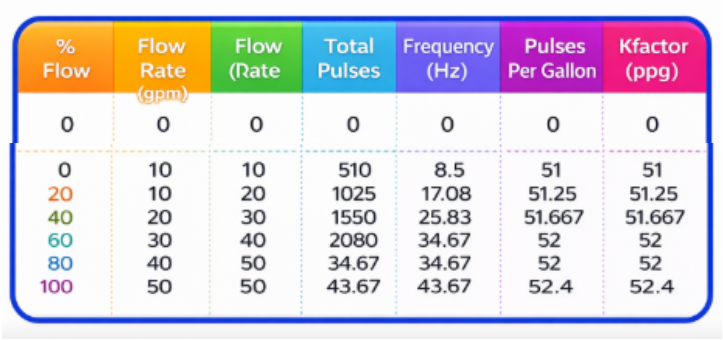
From the provided calibration sheet, we can correlate the flow meter’s frequency output to its K-factor as shown below:
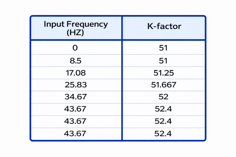
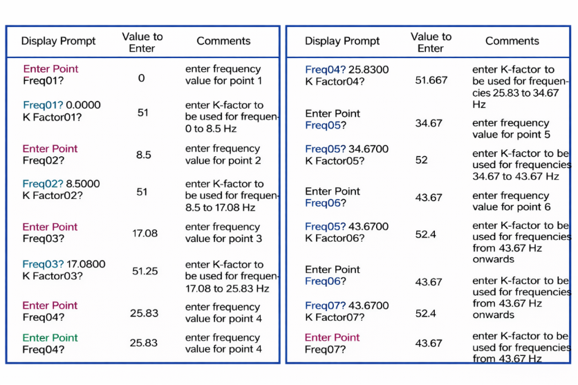
The 16-point K-factor program can be configured as follows:
K-factors for Analog Inputs
Procedure for Analog Input K-Factors
Configuring K-factors for analog input flow meters follows a process similar to that used for pulse-output meters:
- Calculate K-factors for each flow range
Begin by determining the K-factors required for different flow ranges. This can be done using the flow meter manufacturer’s calibration sheet or, alternatively, by performing on-site testing with a calibrated reference standard. - Associate measured flow with K-factors
Once the K-factors are established, link the incoming flow values from the meter to the corresponding K-factor for each flow point. - Program the instrument
Enter the calculated K-factor values into the flow computer, totalizer, or batch controller. The instrument will then automatically adjust its calibration, ensuring accurate flow measurement across the full operating range.
Multi-Point K-Factors in Analog Flow Measurement
For analog flow meters, multi-point K-factors are typically implemented using:
- Lookup tables for pre-defined K-factors at various flow points
- Piecewise linear scaling between flow segments
- Software-based correction curves to compensate for non-linear characteristics
The advantages of this approach include:
- Improved accuracy over the entire operating range
- Compensation for non-linear flow behavior
- Enhanced reliability in critical process applications
This method is commonly employed in DCS-based process plants, where precise flow measurement directly impacts product quality, energy efficiency, and overall process control.
Example 6
The calibration details for a vortex flow meter are given below. The base K-factor is calculated as 10,000 ÷ 100 = 100.
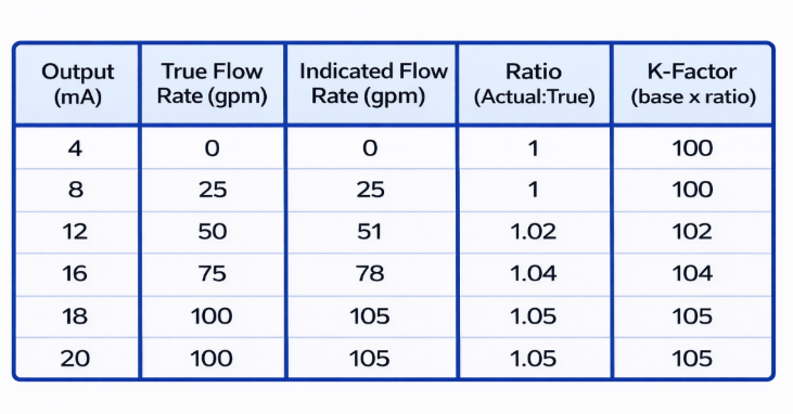
Using a MASStrol flow computer as a reference, the K-factor values are programmed in the following manner.
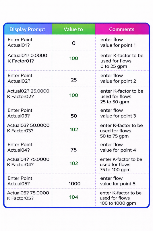
It is important to ensure that the flow value entered after the final calibration point is set significantly higher than the actual maximum operating flow rate of the meter.
Also, since the last two K-factor values are identical, any flow exceeding 100 gpm will continue to be corrected using a K-factor of 104. With this configuration in place, the setup process is complete.
Conclusion
The Flow Meter K-factor plays a vital role in converting raw flow meter signals into accurate and reliable flow data. Whether using pulse signals or analog inputs, selecting and applying the correct K-factor ensures precise flow rate calculation, totalization, and process control. From single-point calibration to advanced multi-point K-factor implementation, a proper understanding of Flow Meter K-factor concepts helps engineers achieve higher accuracy, improved efficiency, and better operational performance in industrial flow measurement systems.
Read Next: