In PLC programming, One Shot Rising (OSR) and One Shot Falling (OSF) instructions are essential for detecting signal changes. OSR triggers a pulse when an input transitions from OFF to ON, while OSF triggers a pulse when an input transitions from ON to OFF. These instructions prevent multiple counts from a single input.
One Shot Rising (OSR)
The One Shot Rising (OSR) instruction triggers an output for only one scan when an input changes from OFF (0) to ON (1). It is used to capture precise transitions and prevent repeated activation from a continuous ON signal.
Key points:
- Found on the right side of a ladder logic rung.
- Requires two bits:
- Storage Bit – monitors the input state.
- Output Bit – generates a single pulse to energize other instructions or outputs.
- Ideal for counting events, triggering timers, or other one-time actions.
Using OSR ensures that your PLC responds once per input change, avoiding multiple counts or repeated actions.
One Shot Falling (OSF)
The One Shot Falling (OSF) instruction energizes an output for just one scan when an input transitions from ON (1) to OFF (0). It is useful for capturing falling-edge events without retriggering during a sustained OFF signal.
Key points:
- Placed on the right side of a ladder logic rung.
- Requires two bits:
- Storage Bit – monitors the input’s previous state.
- Output Bit – generates a single pulse that can trigger other instructions or outputs.
- Commonly used for event counting, timers, or momentary actions that should occur only once per transition.
Using OSF ensures that your PLC responds exactly once when an input goes LOW, avoiding multiple activations from a continuous signal.
PLC Instructions for One Shot Rising and One Shot Falling
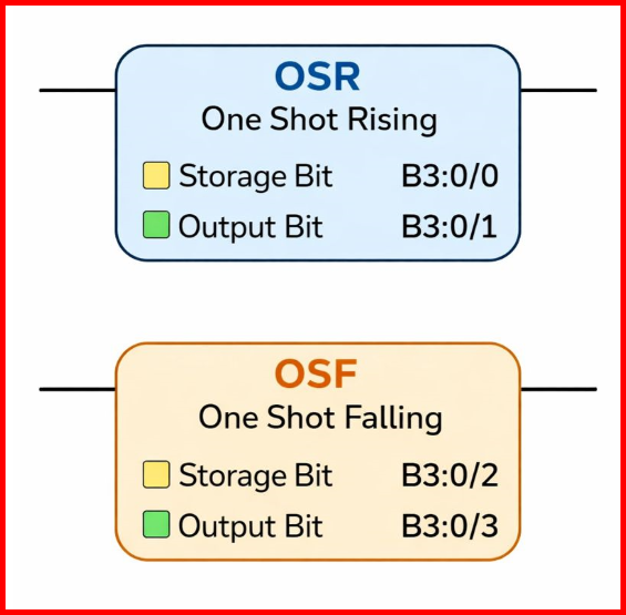
The image below illustrates the instruction blocks for OSR (One Shot Rising) and OSF (One Shot Falling). It visually shows how each instruction generates a single pulse output based on a rising or falling input transition, along with the associated Storage Bit and Output Bit used in ladder logic.
PLC Program using OSR and OSF
Ladder Logic Operation Explained
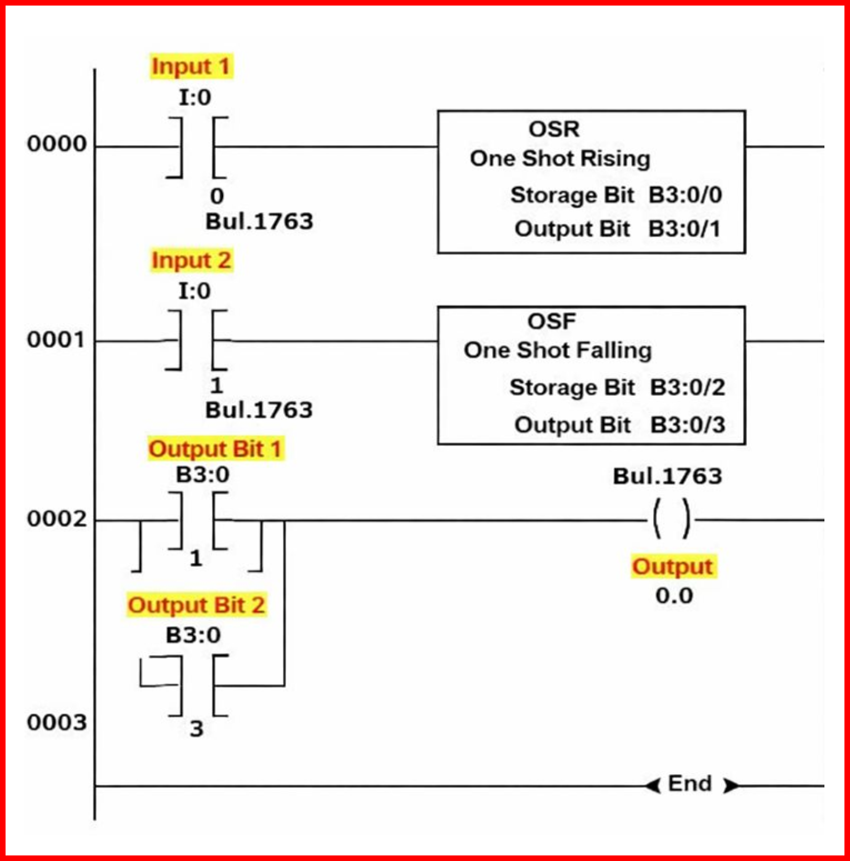
RUNG 0000 – One Shot Rising (OSR)
In this rung, Input 1 (I:0/0) is connected to an OSR (One Shot Rising) instruction. The operation works as follows:
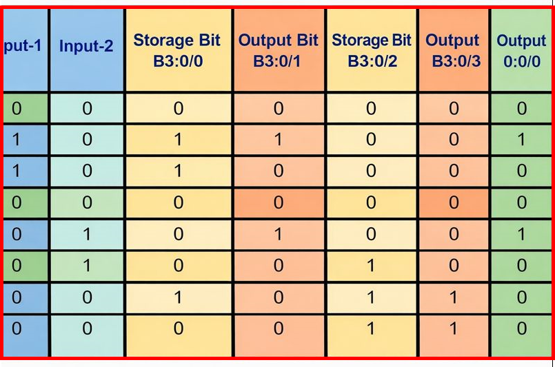
- When Input 1 (I:0/0) transitions from OFF (0) to ON (1), the storage bit (B3:0/0) toggles its state from 0 (Low) to 1 (High).
- Simultaneously, the output bit (B3:0/1) is energized to High (1) for a brief duration (approximately one scan cycle) and then automatically returns to Low (0).
This ensures that the output only activates once per rising edge of the input, preventing continuous triggering if the input remains ON.
RUNG 0001 – One Shot Falling (OSF)
Here, Input 2 (I:0/1) is connected to an OSF (One Shot Falling) instruction. The sequence is as follows:
- When Input 2 (I:0/1) is turned ON, the storage bit (B3:0/2) is set to 1, while the output bit (B3:0/3) stays 0.
- When Input 2 (I:0/1) transitions from ON to OFF, the output bit (B3:0/3) is energized to 1 for a short duration (around one scan cycle) and then returns to 0.
- At the same time, the storage bit (B3:0/2) resets back to 0.
This mechanism allows the output to respond once per falling edge of the input signal, making it ideal for detecting OFF transitions.
Conclusion
Understanding One Shot Rising (OSR) & One Shot Falling (OSF) Instructions in PLC is crucial for precise control in automation systems. These instructions allow a PLC to detect input transitions accurately, generating a single pulse for each rising or falling edge.
By using OSR and OSF effectively, engineers can prevent multiple activations from a continuous signal, ensure reliable event counting, and execute timed or momentary actions with precision. Incorporating these instructions into your ladder logic enhances the efficiency, accuracy, and stability of industrial automation processes.
Read Next: