Understanding PFD vs P&ID is essential for engineers, designers, and plant operators involved in process industries. While both diagrams represent process systems, they serve very different purposes at different stages of engineering design.
A PFD presents the overall process view, highlighting major equipment and the movement of materials through the system. In contrast, a P&ID provides a detailed layout, including piping, valves, instrumentation, and control logic. Understanding this distinction enables engineers and operators to design accurately, operate safely, and maintain reliable process performance.
This article explains the key differences, uses, elements, and real-world relevance of Process Flow Diagrams (PFDs) and Piping & Instrumentation Diagrams (P&IDs) in a simple manner.
What Is a Process Flow Diagram (PFD)?
A Process Flow Diagram (PFD) is a high-level graphical representation of a process that shows the major equipment, process streams, and overall material and energy flow within a plant.
PFDs focus on what happens in the process, not on how it is physically constructed.

Key Purpose of a PFD
- Visualize the overall process
- Understand material and energy balance
- Support conceptual and basic engineering design
- Communicate process logic clearly
Who Uses PFDs?
PFDs are commonly used by:
- Process engineers
- Chemical engineers
- Project managers
- Students and trainees
- Management and decision-makers
They are ideal for discussions during feasibility studies and early project stages.
Common Elements in a PFD
A typical PFD includes:
- Major equipment (reactors, pumps, heat exchangers, columns)
- Process flow lines
- Stream numbers
- Flow rates, temperatures, and pressures
- Energy streams (steam, cooling water)
- Key control loops (basic level only)
Note: PFDs do not include piping details, valve types, or wiring.
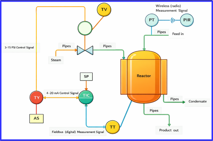
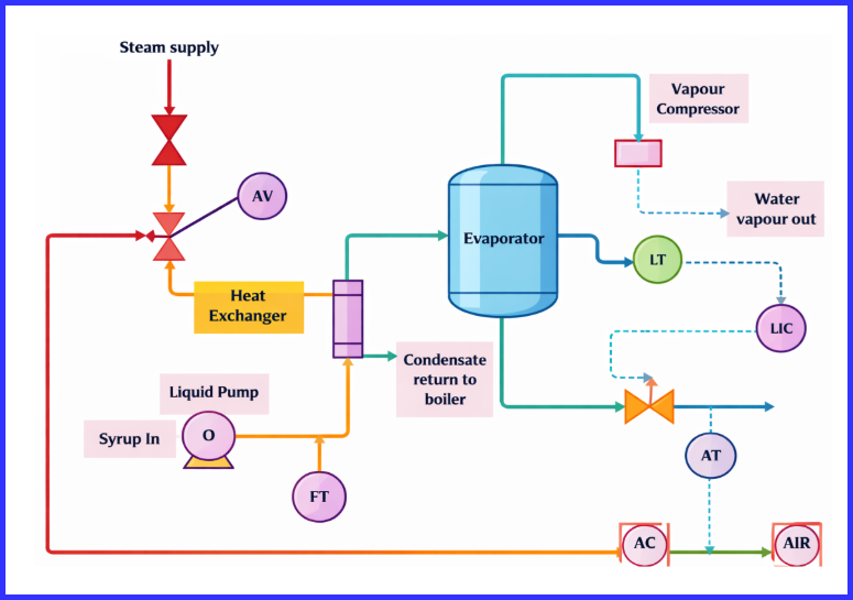
What Is a Piping & Instrumentation Diagram (P&ID)?
A Piping & Instrumentation Diagram (P&ID) is a detailed schematic that illustrates the exact physical layout and control configuration of a process system.
It shows how piping, valves, instruments, and control systems are interconnected, along with line numbers, materials, and equipment tag IDs. By clearly defining how the process is actually built and controlled, P&IDs serve as a critical reference for construction, operation, maintenance, and safety analysis.
Who Uses P&IDs?
P&IDs are used by:
- Instrumentation engineers
- Mechanical engineers
- Electrical engineers
- Maintenance teams
- Operators
- Safety and HAZOP teams
They are critical throughout the plant lifecycle.
Common Elements in a P&ID
A P&ID contains:
- Detailed piping layout
- Pipe sizes and line numbers
- Valves (manual, control, safety)
- Instruments with tag numbers
- Control loops and signal lines
- Equipment tag numbers
- Safety devices (PSVs, rupture disks)
- Utility connections
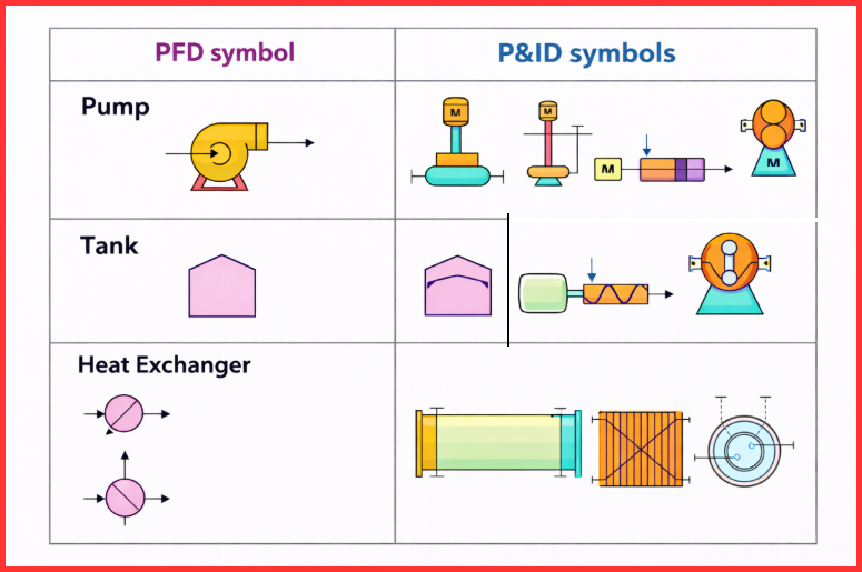
Difference Between a P&ID and a PFD
Although both PFDs and P&IDs are used in process and chemical engineering to illustrate plant systems, they are created for distinctly different objectives.
PFDs provide a high-level view of the process by highlighting major equipment and the movement of materials or energy. Their simplified layout makes them easy to interpret and useful for understanding process logic and planning overall workflows.
P&IDs, on the other hand, present a detailed representation of the system, showing every pipe, valve, instrument, and control loop. These diagrams are indispensable during construction, operation, and maintenance, as they define exactly how the process is built and controlled.
This difference exists because each diagram supports a specific phase of the engineering lifecycle—PFDs aid in process design and conceptual understanding, while P&IDs ensure precise, safe, and reliable implementation and operation.
Tabular Summary: Difference Between a P&ID and a PFD
| Feature | PFD (Process Flow Diagram) | P&ID (Piping & Instrumentation Diagram) |
| Primary purpose | Presents the overall process flow and major process steps | Defines detailed piping layouts, instrumentation, and control systems |
| Level of detail | High-level and simplified | Highly detailed and comprehensive |
| Equipment representation | Displays only major equipment | Shows all equipment with unique tag numbers |
| Piping information | Limited to main process connections | Includes pipe sizes, line numbers, fittings, and materials |
| Valves | Not shown or represented generically | All manual, control, and safety valves are clearly indicated |
| Instrumentation | Basic instrumentation for process understanding | Complete instrumentation with tags and control loops |
| Control and operation | Provides an overview of process logic | Defines exact control logic and interlocks |
| Typical usage | Concept development and process design | Construction, operation, and maintenance |
| Safety analysis | Limited use in safety reviews | Essential for HAZOP, risk assessment, and safety compliance |
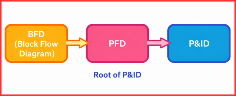
How PFDs and P&IDs Fit into the Engineering Design Flow
Understanding PFD vs P&ID becomes easier when viewed as part of the overall engineering workflow.
1. Start with a Block Flow Diagram (BFD)
- Simplest form of process representation
- Shows major process blocks only
- Used for early concept discussions
2. Create a Process Flow Diagram (PFD)
- Adds major equipment and process streams
- Includes operating conditions
- Used for mass and energy balance
- Forms the foundation for detailed design

3. Develop the Piping & Instrumentation Diagram (P&ID)
- Expands the PFD into detailed piping and control
- Defines how the plant will be built and operated
- Used for procurement, construction, and commissioning
4. Understand the Flow from Concept to Implementation
- BFD → PFD → P&ID → Construction → Operation
- Each step adds more detail and accuracy to the design.
Conclusion
In summary, understanding PFD vs P&ID is essential for anyone involved in process design and plant engineering. A PFD provides a clear overview of how a process works, while a P&ID delivers the detailed blueprint required to build, operate, and maintain that process safely and efficiently. Both diagrams are not competitors but complementary tools, each playing a vital role from concept to implementation.
FAQs About P&ID and PFDs
You should always start with a PFD before creating a P&ID. The PFD defines the process logic that the P&ID expands into detail.
No. A PFD cannot replace a P&ID because it lacks detailed piping, instrumentation, and safety information required for construction and operation.
PFDs are important because they:
-Explain the process clearly
-Support process calculations
-Help in early design decisions
-Improve communication between teams
P&IDs are critical because they:
-Define exact plant configuration
-Support safe operation
-Enable maintenance and troubleshooting
-Are mandatory for HAZOP and safety reviews
Yes. PFDs and P&IDs are widely used in:
-Oil and gas
-Chemical plants
-Power plants
-Water and wastewater treatment
-Pharmaceuticals
-Food and beverage industries
Read Next: