A PLC Conveyor Motor Ladder Logic is widely used in industrial automation to control conveyor belt motors in a safe, reliable, and sequential manner. In a modern PLC conveyor system, ladder logic helps automate material handling by ensuring motors start, stop, and operate according to predefined conditions. Whether it is packaging, assembly, or bulk material handling, a well-designed conveyor control system improves productivity and minimizes human error.
PLC Conveyor Motor Ladder Logic
In industrial plants, conveyors are controlled using PLCs instead of traditional hardwired relay logic. A PLC conveyor program replaces complex wiring with software logic, making troubleshooting and modification easier. The ladder diagram visually resembles electrical relay circuits, which makes it easy for maintenance engineers to understand.
The conveyor PLC logic generally includes start/stop control, interlocks, overload protection, and sequential operation. These elements ensure safe and efficient motor operation.
Objective: The Sequential Tasks as Follows
The main objective of a PLC-based conveyor motor control is to perform tasks in a defined sequence. Typical objectives include:
- Starting the conveyor motor using a push button
- Stopping the conveyor safely using a stop switch
- Providing motor latching (seal-in) logic
- Protecting the motor using overload contacts
- Ensuring proper ON and OFF sequence
- Improving reliability compared to relay-based systems
In a PLC conveyor system, these tasks are executed automatically with high accuracy.
Relay Schematic of PLC Conveyor
Before PLCs were widely used, conveyor motors were controlled using relay logic. Understanding the relay schematic helps in designing an effective conveyor ladder logic.
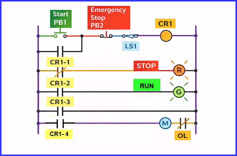
A typical relay schematic includes:
- R : STOP Indication lamp,
- G : RUN Indication lamp,
- M : Motor,
- OL : Overload Relay (Motor Protection Relay),
- LS1 : Proximity Switch
- PB1 : Start push button,
- PB2 : Emergency Stop Pushbutton,
- CR : Contractor Relay
This relay schematic is converted directly into PLC ladder logic. Each relay contact is mapped to a PLC input, and the contactor coil is mapped to a PLC output.
Operational Sequence
The operational sequence of a conveyor motor using PLC logic is as follows:
- The operator presses the START push button.
- The PLC verifies that the STOP push button and overload protection contacts are in a healthy state.
- Once all safety conditions are satisfied, the PLC energizes control relay CR1.
- Contact CR1-1 closes, forming a seal-in path that latches the start command and keeps the system running.
- Contact CR1-2 opens, turning OFF the red stop indicator lamp.
- Contact CR1-3 closes, switching ON the green run indicator lamp.
- Contact CR1-4 closes, energizing the motor starter and starting the conveyor motor.
- The motor continues running due to the latching logic until a stop condition occurs.
- As the conveyor moves, the box or package travels forward.
- When the box reaches the sensing point, proximity switch LS1 detects it and signals the PLC to de-energize relay CR1.
- Contact CR1-1 opens, removing the seal-in path and unlatching the start command.
- Contact CR1-2 closes, switching the red pilot lamp ON.
- Contact CR1-3 opens, turning the green pilot lamp OFF.
- Contact CR1-4 opens, de-energizing the motor starter, stopping the conveyor motor, and completing the operating sequence.
This integrated sequence clearly represents how PLC logic, latching control, safety checks, and field devices work together to form a reliable conveyor control system.
PLC Ladder Logic
The PLC Conveyor Motor Ladder Logic is shown below,
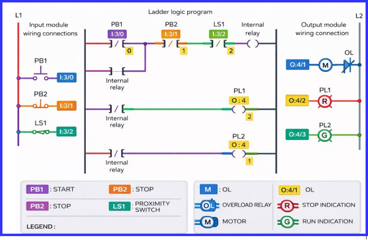
The image illustrates a PLC conveyor motor ladder logic program along with its corresponding input and output wiring connections. The diagram is divided into three main sections: the input side (L1), the ladder logic program, and the output side (L2).
On the input module side, three field devices are connected to the PLC inputs:
- PB1 (I:3/0) – Start push button
- PB2 (I:3/1) – Stop push button
- LS1 (I:3/2) – Proximity switch used for box detection
The first rung of the ladder logic represents the start–stop and latching circuit. When PB1 is pressed, the internal relay coil is energized, provided PB2 and LS1 are in their normal states. An internal relay contact is used as a seal-in contact to maintain the run command even after releasing the start button.
The second and third rungs control the pilot lamps. When the internal relay is de-energized, PL1 (O:4/2), the red stop indication lamp, is energized. When the relay is energized, PL2 (O:4/3), the green run indication lamp, turns ON, indicating that the conveyor is running.
The final rung controls the conveyor motor output M (O:4/1). When the internal relay is active, the PLC energizes the motor output, which drives the motor through an overload relay (OL). The overload relay provides protection by disconnecting the motor in case of excessive current.
Overall, this ladder logic diagram demonstrates a simple yet effective PLC-based conveyor control system, integrating start–stop control, latching logic, sensor-based stopping using a proximity switch, motor protection, and visual status indication through pilot lamps.
Advantages of PLC-Based Conveyor Control
- Easy modification without rewiring
- Faster troubleshooting
- High reliability and accuracy
- Better integration with sensors and automation systems
- Suitable for complex conveyor PLC applications
Conclusion
A well-designed PLC Conveyor Motor Ladder Logic plays a crucial role in modern industrial automation. By replacing traditional relay circuits, a PLC-based PLC conveyor system offers flexibility, safety, and efficient control of conveyor motors. Understanding the relay schematic, operational sequence, and ladder logic helps engineers design a reliable conveyor control system that meets industrial demands while ensuring smooth and safe material handling operations.
Read Next: