The PLC latching function is one of the most commonly used logic techniques in industrial automation. It allows an output to remain energized even after the initiating input signal is removed. This behavior is essential in real-world applications where machines must continue running until a deliberate stop command is given.
In simple terms, a PLC latch creates a memory effect inside the control program.
What Is a PLC Latching Function?
A PLC latching function is a self-holding logic arrangement in which an output maintains its ON or OFF state until a specific reset or stop condition occurs. Once latched, the output does not depend on the original input signal anymore.
This function is widely used in:
- Motor start/stop circuits
- Conveyor systems
- Pumps and fans
- Machine start-up sequences
Why Is Latching Required in PLC Systems?
In many industrial situations, input devices such as push buttons are momentary. They send a signal only while being pressed. However, machines like motors or pumps are required to keep running continuously.
Practical Example
Consider a motor controlled by:
- A START push button (momentary)
- A STOP push button (momentary)
If the motor depended only on the START button, it would stop as soon as the button was released. A latching circuit solves this problem by holding the motor output ON until the STOP button is pressed.
Basic Principle of PLC Latching
The core idea behind PLC latching is feedback logic.
- An input (START) energizes an output (motor coil).
- A contact linked to the same output is placed in parallel with the START input.
- Once the output turns ON, its own contact keeps the circuit energized.
- A STOP input breaks the circuit and resets the latch.
This logic behaves like an OR condition, where either the START input or the latched output contact can maintain the output state.
PLC Latching Ladder Logic (Conceptual)
A basic PLC latching ladder logic consists of:
- Normally Open (NO) START contact
- Normally Closed (NC) STOP contact
- Output coil
- Self-holding contact of the output
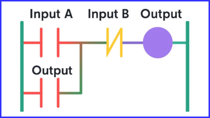
When the START button is pressed, the output coil energizes. Its auxiliary contact closes and bypasses the START button, keeping the output ON. Pressing the STOP button opens the circuit and turns the output OFF.
Motor Control Using PLC Latching Logic
Scenario
A motor is controlled using:
- START push button
- STOP push button
- Two indicator lamps:
- Motor ON lamp
- Motor OFF lamp
Operation Logic
- At PLC startup, the STOP input is active (normally closed), ensuring safe operation.
- Pressing the START button energizes the motor output.
- The motor output latches itself using its own contact.
- The ON lamp turns ON and the OFF lamp turns OFF.
- Pressing the STOP button breaks the latch.
- The motor stops, ON lamp turns OFF, and OFF lamp turns ON.
This approach is safer than programming STOP inputs as normally closed contacts in software alone, as it ensures fail-safe behavior during wiring faults.
Set/Reset (SR) Latching in PLC
Apart from contact-based latching, many PLCs provide SET (Latch) and RESET (Unlatch) instructions.
Advantages of Set/Reset Latching
- Cleaner ladder logic
- Easy troubleshooting
- Reduced contact clutter
- Better scalability for large programs
Typical Use
- SET instruction → turns output ON
- RESET instruction → turns output OFF
This method is commonly used in Siemens, Allen-Bradley, Mitsubishi, and Schneider PLCs.
Advantages of PLC Latching Function
- Maintains output state without continuous input
- Reduces wiring complexity
- Improves operational safety
- Ideal for machine start-up logic
- Widely supported across all PLC platforms
Common Applications of PLC Latching
- Motor start/stop control
- Pump and fan systems
- Alarm acknowledgment circuits
- Emergency stop logic (with safety interlocks)
- Manual/auto mode selection
- Machine cycle hold functions
Practical Application Example:
To demonstrate the practical use of a latching circuit, consider a motor operated using START and STOP push-button switches. In this system, one indicator lamp is designed to turn ON when the motor is energized, while a second lamp lights up whenever the motor is switched OFF.

In this circuit, the stop input X401 is programmed as a normally open contact. When a normally closed stop pushbutton is used in the field, X401 receives a signal during startup that causes the contact to close. This approach is considered safer than programming X401 as a normally closed contact in the PLC logic because any wiring fault or loss of power will naturally stop the system.
At program start, X401 is already closed. When the start pushbutton X400 is pressed momentarily, output Y430 is energized. Once Y430 turns ON, its auxiliary contacts close, creating a latching path that keeps the motor energized even after X400 is released. At the same time, the “power not applied” indicator Y431 turns OFF, while the “power applied” indicator Y432 turns ON, clearly showing the running status of the motor.
To stop the motor, the stop switch X401 is pressed. This action opens X401, causing output Y430 to de-energize. As a result, the Y430 contacts open in the first and third rungs and close in the second rung. Consequently, Y431 switches ON to indicate that power is removed, and Y432 switches OFF, confirming that the motor has stopped.
Latching circuits are widely used in industrial start-up applications because they allow a system to remain ON after a brief start command, ensuring stable and reliable operation without requiring the operator to hold the start button continuously.
Best Practices for Using Latching in PLCs
- Always use normally closed STOP inputs for safety
- Clearly label latched outputs in documentation
- Avoid unnecessary multiple latches for the same output
- Use Set/Reset instructions for complex systems
- Reset all latches during system initialization if required
Conclusion
The PLC latching function is a fundamental building block in PLC programming. It enables machines and processes to continue operating independently of momentary input signals, ensuring stable and reliable control. Whether implemented using self-holding contacts or SET/RESET instructions, latching logic plays a critical role in motor control, automation safety, and industrial efficiency.
A strong understanding of PLC latching not only improves program reliability but also makes troubleshooting and system expansion much easier.
Read Next: