PLC Programming Examples play a crucial role in understanding real-time industrial automation processes. In this PLC Programming Examples article, we explain a practical Siemens PLC ladder logic where a saw, fan, and oil pump operate based on timing conditions, stop events, and reset logic. This example clearly demonstrates how timers, memory bits, comparator blocks, and outputs work together in an industrial PLC program.
PLC Programming Examples
This PLC programming example focuses on the following operating conditions:
- A Saw, Fan, and Oil Pump turn ON when the Start push button is pressed.
- If the saw runs for less than 20 seconds, the oil pump turns OFF immediately, and the fan runs for an additional 5 seconds after the saw stops.
- If the saw runs for more than 20 seconds, the fan remains ON until reset by a Fan Reset Button, and the oil pump runs for an additional 10 seconds after the saw stops.
- The logic is implemented using timers (T4:0, T4:1, T4:2), memory bits, and comparator blocks.
Program Description:
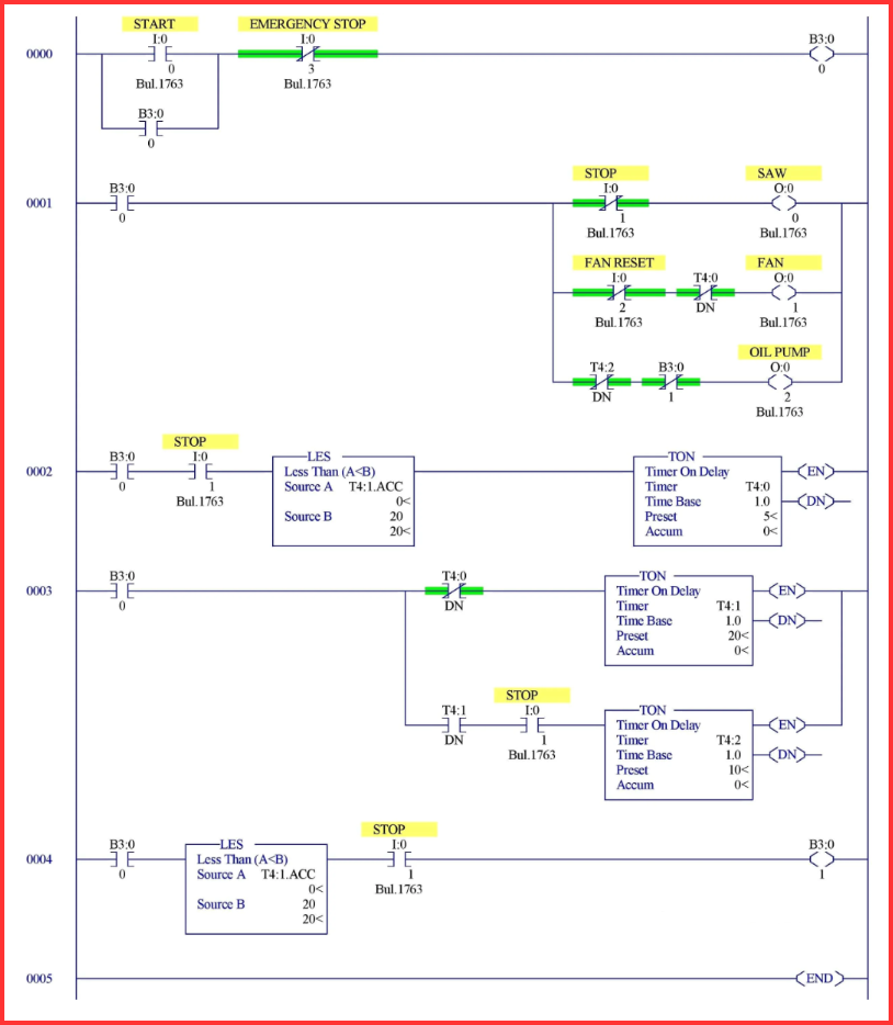
Rung 0000:
The Start Push Button and Emergency Stop Push Button are latched using memory bit B3:0/0.
This memory bit acts as a seal-in circuit to maintain the system run condition until a stop event occurs.
Rung 0001:
When B3:0/0 is enabled, it turns ON:
- Saw output (O:0/0)
- Fan output (O:0/1)
- Oil Pump output (O:0/2)
A normally closed contact of the Stop switch is placed in series with the Saw output, ensuring the saw turns OFF immediately when the stop switch is pressed.
The Fan Reset Switch along with Timer T4:0 logic is used to turn OFF the fan when conditions are met.
The done bit of Timer T4:2 and a memory bit are used to turn OFF the oil pump after the required delay.
Rung 0002:
When the Stop switch is pressed, the fan behavior depends on the saw operating time.
- If the saw has run less than 20 seconds, the Fan output (O:0/1) turns OFF after 5 seconds.
- A Comparator block is used to ensure that Timer T4:0 is enabled only after 20 seconds of saw operation.
This rung ensures correct fan delay logic based on saw runtime.
Rung 0003:
Timer T4:1 starts running when the Start Push Button is pressed and tracks the saw operating time.
- If the stop is pressed after 20 seconds, the Saw output turns OFF immediately.
- Timer T4:2 then starts and turns OFF the Oil Pump after 10 seconds.
- The done bit of Timer T4:0 is used to restrict Timer T4:1 operation once the 20-second condition is achieved.
This rung controls delayed oil pump shutdown for long saw operations.
Rung 0004:
A Less-Than Comparator block is used to detect when the saw operating time is less than 20 seconds.
Based on this comparison:
- The Fan output is turned OFF after 5 seconds, satisfying the short-run condition logic.
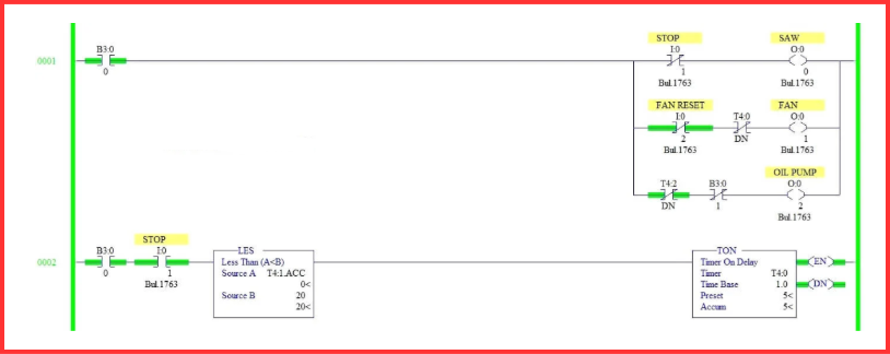
Program Output:
Below is the operational behavior of the PLC program under different conditions.
When Start PB is pressed
- Memory bit B3:0/0 is latched.
- Saw, Fan, and Oil Pump outputs turn ON.
- Timers begin tracking saw operation time.

All devices start running together.
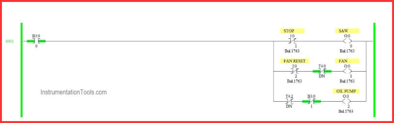
When Stop switch pressed before the 20s

- Saw turns OFF immediately.
- Oil pump turns OFF instantly.
- Fan runs for 5 additional seconds, then turns OFF.
Short-run shutdown logic applied.
When Stop switch pressed after the 20s
- Saw turns OFF immediately.
- Oil pump remains ON for 10 seconds, then turns OFF.
- Fan remains ON continuously.
- Fan turns OFF only when the Fan Reset Switch is pressed.
Long-run shutdown logic activated.
When Fan reset switch is pressed
- Fan output turns OFF.
- System returns to a ready state for the next operation cycle.
Manual fan reset completed.
Conclusion:
This PLC Programming Examples article clearly demonstrates how timers, memory bits, comparator blocks, and outputs are used to build real industrial logic in a Siemens PLC environment. Such PLC Programming Examples are extremely useful for understanding conditional timing control, delayed shutdown logic, and safe machine operation.
By practicing PLC Programming Examples like this, engineers and technicians can confidently design and troubleshoot complex industrial automation systems using structured ladder logic.
Read Next: