A restricted flow orifice is a simple yet critical flow-control device widely used in process industries to limit flow, reduce pressure, and protect downstream equipment. Unlike flow-measuring devices, a restriction flow orifice is designed only to restrict flow at a predetermined rate. Due to its reliability, low cost, and maintenance-free operation, the restriction orifice plate is commonly installed in gas, liquid, and steam lines.
This article explains the restriction orifice working principle, types, applications, sizing, calculations, flow direction, and relevant codes and standards.
Restriction Orifice
A restriction orifice (also called a restriction plate or pressure reducing orifice plate) is a thick metal plate with a precisely machined bore installed in a pipeline to create a permanent pressure drop. The orifice pressure drop limits the flow rate to a safe and controlled value.
Unlike an orifice plate used for flow measurement, a calibrated orifice used for restriction does not require transmitters or flow calculation during operation. Once installed, the flow remains fixed based on upstream conditions.
Restriction Orifice Working Principle
The restriction orifice working principle is based on energy conversion:
- Fluid accelerates as it passes through the orifice bore
- Velocity increases and static pressure decreases
- Energy loss occurs due to turbulence
- A permanent pressure drop is created
This controlled loss of pressure limits the flow rate and protects downstream piping, valves, and equipment.
Types of Restriction Orifice Plates
Single-stage Restriction Orifice
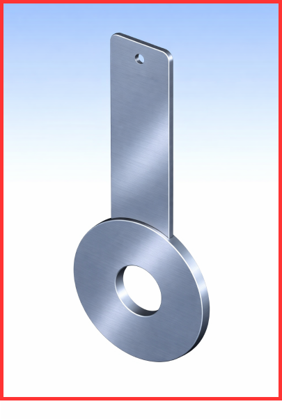
A single-stage restriction orifice is typically manufactured as a solid plate or compact metal block with a precisely machined bore designed to produce a predetermined permanent pressure drop. It is installed between pipeline flanges and remains fixed during operation. Unlike a thin orifice plate used for flow measurement, this restriction orifice is comparatively thick.
Key points:
- Uses one thick plate to create the required pressure drop
- Suitable for low to moderate pressure drops
- Commonly used in liquid services
- Ideal for simple system designs
Limitation:
- Very high pressure drops may lead to noise, vibration, or cavitation
Single-stage Multi-hole Restriction Orifice
A single-stage multi-hole restriction orifice plate is designed to control high-velocity flow while minimizing noise and vibration. Instead of forcing the entire flow through a single opening, it divides the total flow into multiple small jets, each passing through precisely machined holes. This distribution reduces local velocity, turbulence, and mechanical stress on the plate.
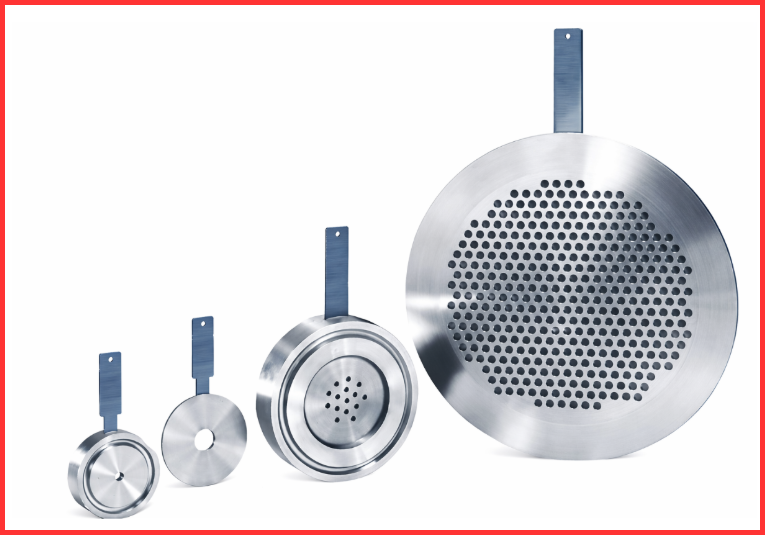
Advantages:
- Reduced vibration in the piping system
- Lower noise generation compared to single-hole designs
- Better energy dissipation across the orifice
Due to these benefits, single-stage multi-hole restriction orifices are widely used in high-velocity gas services where noise control is a critical requirement.
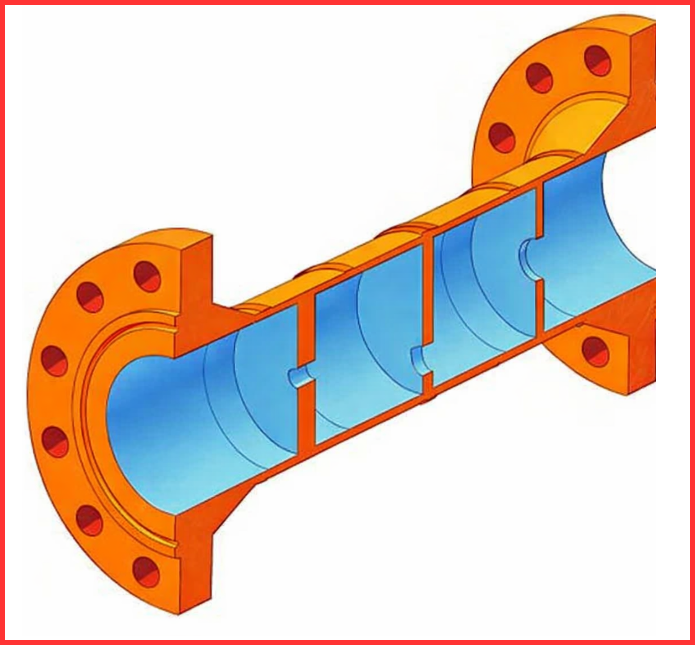
Multi-stage Restriction Orifice Plate Assembly
These devices are applied in services where the required pressure reduction is extremely high and cannot be safely or effectively handled by a single-stage restriction orifice. A multi-stage restriction orifice plate assembly therefore uses multiple restriction plates arranged in series within a single spool piece, allowing the total pressure drop to be divided into several stages.
Similar to single-stage designs, multi-stage restriction orifices may be configured as single-hole multi-stage, multi-hole multi-stage, or a hybrid combination of both, depending on process requirements.
Benefits:
- Prevents cavitation and flashing
- Controls erosion and plate wear
- Ideal for very high differential pressure applications
Due to these advantages, multi-stage restriction orifices are widely used in blowdown and depressurization systems.
Conical-shaped Restriction Orifice Plate
A conical-shaped restriction orifice plate is specifically designed to address issues related to orifice cavitation, including erosion, vibration, and excessive noise. Its tapered bore improves flow stability and significantly reduces wear compared to sharp-edged designs.
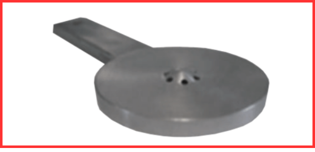
In this type of orifice, flow energy is dissipated inside the conical section rather than at the pipe wall, allowing the fluid to recover smoothly before entering the downstream piping. This controlled dissipation minimizes cavitation damage and protects the pipe wall from direct impingement.
Key features:
- Smooth pressure recovery
- Lower turbulence and noise
- Longer service life due to reduced erosion
Restriction Orifice Plate Flow Direction
The restriction orifice plate flow direction is critical for proper operation.
Most restriction plates have:
- An engraved arrow
- A beveled or conical inlet side
Incorrect installation can cause excessive erosion and inaccurate pressure drop.
Restriction Orifice vs Orifice Plate
| Parameter | Restriction Orifice | Orifice Plate |
| Purpose | Flow limiting | Flow measurement |
| Pressure drop | Permanent | Measured |
| Instrumentation | Not required | Required |
| Accuracy | Fixed flow | High accuracy |
| Maintenance | Minimal | Periodic calibration |
Applications of Restriction Orifice Plates
Below are some typical applications where restriction orifice devices are used to maintain controlled and predictable flow between upstream and downstream systems.
In many of these services, restriction orifices operate under severe flow conditions, including very high pressure drops. Such conditions may lead to liquid flashing, cavitation, or sonic (choked) flow. Therefore, these flow and fluid behavior effects are carefully evaluated during the design and selection of restriction orifices to ensure safe, reliable, and long-term operation.
Restriction Orifice (RO) at the Downstream of Blowdown Valves
Restriction orifices are installed in blowdown piping or blowdown headers downstream of blowdown valves to ensure a controlled discharge during depressurization events.
When a blowdown valve—typically a full-bore (FB) or reduced-bore (RB) ball valve—opens to relieve high upstream pressure, the restriction orifice plate limits the flow so that the depressurization rate is controlled, noise and vibration are reduced, and the flare header is protected from overloading.
In blowdown systems, the pressure drop across the restriction orifice can be extremely high, often in the range of 80 to 100 bar. If such a large pressure reduction is handled by a single-stage device or by a design with insufficient staging, a significant temperature drop can occur during blowdown due to the Joule–Thomson effect.
Therefore, restriction orifice design must also account for low-temperature conditions to ensure material integrity and safe, reliable operation.
Restriction Orifice (RO) in Pump Re-circulation Line
Restriction orifices are commonly installed in the recirculation line of centrifugal pumps where a fixed minimum flow is required and precise control of recirculation or forward flow is not critical. In such applications, the restriction orifice maintains a steady bypass flow without the need for active control devices.
Used to:
- Maintain minimum pump flow
- Prevent overheating
- Avoid pump damage
This continuous recirculation ensures that the pump operates above its minimum flow limit, thereby preventing cavitation and suction starvation and protecting the pump from thermal and mechanical damage.
Restriction Orifice (RO) to Restrict Gas Blow-by
A common application of restriction orifices is in controlling the flow of hydrocarbon condensate from a high-pressure separator to a low-pressure separator. Typically, a level control valve (LCV) regulates the liquid level in the high-pressure separator. However, if the valve fails, it may open fully to prevent the separator from overflowing.
When the LCV is fully open, a large volume of condensate flows downstream, often accompanied by gas. To prevent the downstream relieving system from being overloaded by this sudden surge, a restriction orifice is installed immediately downstream of the LCV to limit the flow.
A similar principle is applied in heating medium lines to re-boilers, where the restriction orifice mitigates the effects of a heating medium valve failing open, ensuring the downstream system is protected from excessive flow.
Restriction Orifice (RO) to Check Excess Flow
Restriction orifices are also employed as a safety measure to limit excessive flow during rupture events.
For example, in wellhead applications, if the downhole valves need to be closed due to a fire or emergency, a fusible plug is used to depressurize the hydraulic oil supplying the valve actuator.
When the plug melts, the hydraulic oil is allowed to escape through a restriction orifice, ensuring the flow is controlled at a safe, restricted rate rather than discharging freely, thereby protecting the system and equipment from potential damage.
Restriction Orifice (RO) for Controlled Pressurization
During the start-up of a process plant, several sections need to be pressurized gradually with the incoming process fluid to prevent damage. Typically, the upstream pressure is significantly higher than the downstream, and without flow control, the initial surge can be excessive, potentially harming pipelines, valves, and other equipment.
Restriction orifices (ROs) are used to ensure controlled and gradual pressurization. In gas systems, the optimal design often targets choked flow conditions, where the flow rate becomes limited. Under choked flow, the mass flow rate depends primarily on the square root of the upstream pressure rather than the full differential pressure, effectively restricting the flow and protecting the system during start-up
Codes and Standards
Although there are no internationally recognized standards that specifically govern restriction orifices, several related references and codes are commonly used in design and engineering practice. Key references include:
- ISO 5167 Part 1 – Measurement of fluid flow by means of pressure differential devices inserted in circular cross-section conduits running full: General principles and requirements.
- ISO 5167 Part 2 – Measurement of fluid flow by means of pressure differential devices inserted in circular cross-section conduits running full: Orifice plates.
- IEC 60534-8-3 – Industrial-process control valves: Part 8-3, Noise considerations – Control valve aerodynamic noise prediction method.
Additionally, restriction orifices are often designed following established industrial codes to ensure safety, reliability, and optimal performance, including:
- ASME MFC-3M – Orifice devices
- ISO 5167 – Flow restrictions and plates
- API RP 520 / 521 – Blowdown and depressurization
- ASME B31.3 – Process piping
These standards and codes provide guidance on flow measurement, orifice design, pressure drop, and noise considerations, making them essential references for engineers applying restriction orifices in industrial systems.
Conclusion
A restricted flow orifice is a simple, reliable, and cost-effective solution for controlling flow and pressure in industrial piping systems. When properly designed using correct restriction orifice calculation, accurate sizing, correct restriction orifice plate flow direction, and applicable standards, it delivers long-term, maintenance-free performance. Understanding the restriction orifice vs orifice plate difference ensures correct application and safe system design.
Read Next: