The term SAMA stands for Scientific Apparatus Makers Association. A SAMA diagram is a specialized tool used in industrial plants to represent process control systems in more detail than standard diagrams. Essentially, it is a visual representation using scientific apparatus symbols and functional blocks to indicate specific operations and control functions.
These diagrams are particularly valuable in industrial automation, where binary symbols and structured logic help engineers understand complex processes efficiently.
In industrial instrumentation and control, SAMA diagrams employ a standardized set of symbols to convey information clearly. This system simplifies the design, selection, operation, and maintenance of process control equipment.
Symbols in Process Control
SAMA diagrams rely on a consistent set of symbols that represent various functional elements of process control. These symbols allow engineers to illustrate logic, measurements, and control strategies in a clear and standardized format.
History of the SAMA Diagram
The Scientific Apparatus Makers Association (SAMA) is a professional organization of manufacturers of scientific instruments and equipment. Founded in 1918, SAMA has been instrumental in standardizing symbols and diagrams for industrial control systems.
The association focuses on designing, manufacturing, and distributing instruments and equipment for measurement, analysis, and control. Due to the complex nature of modern control strategies, SAMA diagrams have become essential for documenting detailed operational logic. The standard symbols defined by SAMA help illustrate control signal processing effectively.
Seven Key Sections of SAMA
SAMA organizes its symbols and equipment into seven main categories:
- Analytical Instruments – Devices used for chemical and physical analysis.
- Measuring and Testing Instruments – Tools for precise measurement and evaluation.
- Laboratory Apparatus – Equipment commonly used in lab environments.
- Optical and Nuclear Instruments – Specialized instruments for optical or nuclear applications.
- Process Measurement and Control Instruments – Devices used in industrial process monitoring and control.
- Furniture – Lab and plant furniture supporting instruments and operations.
- Scientific Laboratory Equipment – Additional tools and machinery used for scientific research and experiments.
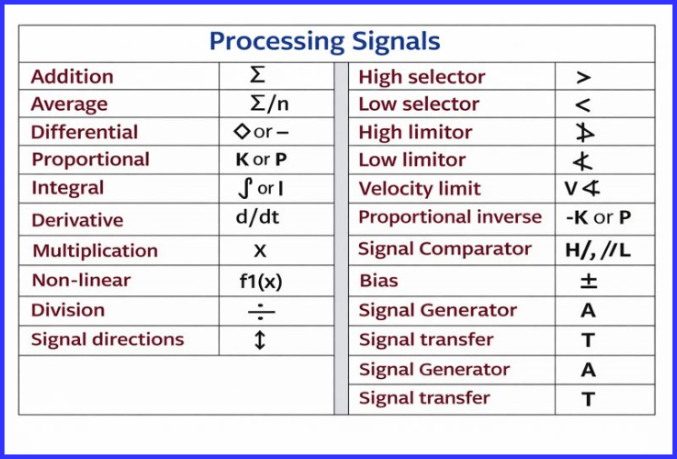
These categories help organize the processing signals and functional elements of the SAMA diagram.
The SAMA diagram utilizes the following set of processing signals.
Why SAMA Diagrams are Popular
In industries like power generation, process control can involve highly complex strategies, particularly for operations such as combustion control. Traditional process diagrams or ISA-standard P&IDs often cannot capture this complexity. SAMA diagrams, with their detailed functional symbols, provide a higher-level visualization of control systems, making them ideal for:
- Boiler functional diagrams
- Combustion control systems
- Complex signal processing loops
Visually, SAMA diagrams resemble flowcharts, where symbols represent individual functions, and the sequence of operations in a loop is clearly depicted. This allows engineers to understand logical sequences and control interactions at a glance.
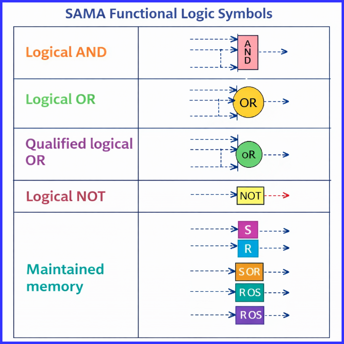
SAMA Functional Logic Symbols
SAMA uses functional logic symbols to represent various operations in control loops. These symbols, combined with labels and mathematical control algorithms, provide a complete picture of complex control logic.
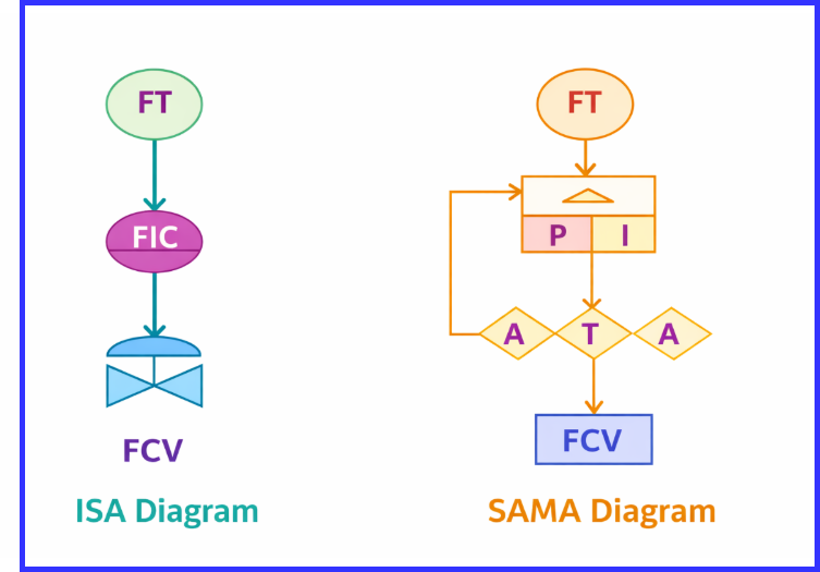
A typical SAMA diagram can be compared to an ISA diagram, but it provides greater detail for control elements and is easier to interpret for engineers working on advanced process systems.
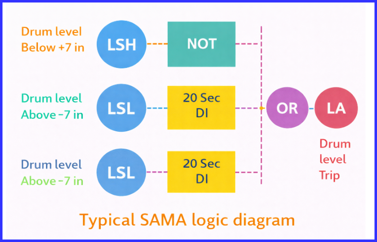
A typical illustration of a SAMA logic diagram is depicted in the image below.
SAMA Drawings
A standard SAMA drawing consists of:
- Functional symbols for processes and instruments
- Labeling systems using series of letters for identification
- Control algorithms for logic description
These elements work together to fully describe the control strategy and operational logic of industrial processes.
Conclusion
SAMA diagrams remain an essential tool in modern industrial automation, particularly for engineers managing complex systems like boilers, combustion units, and large-scale process controls. Their clarity, detail, and standardized symbology make them a cornerstone of process instrumentation documentation.
Read Next: