Understanding the types of control valves and their characteristics is crucial for selecting the right valve for any industrial application. The choice between air-to-open or air-to-close valves ensures the correct fail-safe response during emergencies.
Similarly, deciding between single-seated and double-seated designs depends on whether tight shut-off or high-flow capacity is needed. Flow characteristics such as linear, equal-percentage, and quick-opening help match the valve behavior to the process requirements.
Selecting the right type of control valve not only improves process accuracy and stability but also enhances safety, reduces energy consumption, and prolongs equipment life. With proper sizing, installation, and maintenance, control valves become a reliable backbone of industrial automation and process control.
What is a Control Valve?
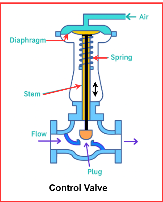
A control valve is a mechanical device used to regulate the flow rate of a fluid in a pipeline by varying the size of the flow passage. The valve receives a signal from a process controller and changes its opening accordingly using an actuator.
A control valve generally consists of:
- Valve Body – Contains the flow passage and seat
- Plug / Disk – Moves to open or close the flow
- Valve Seat – Surface against which the plug seals
- Valve Stem – Connects plug to actuator
- Actuator – Converts control signal into mechanical motion
- Positioner – Ensures accurate valve positioning
The actuator can be pneumatic, electric, or hydraulic, depending on the application.
Why Control Valves Are Important in Process Control
Control valves:
- Maintain process stability
- Improve product quality
- Ensure plant safety
- Reduce energy consumption
- Prevent equipment damage
Without proper control valves, processes could become unstable, unsafe, or inefficient.
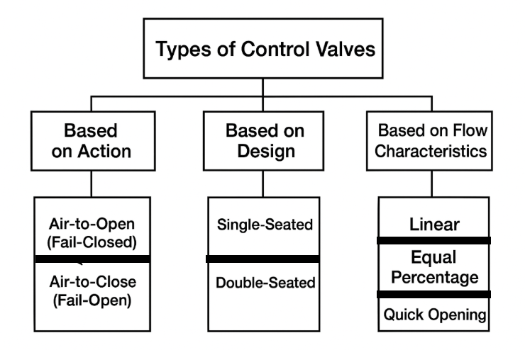
1. Types of Control Valves Based on Action
Pneumatically operated control valves respond to air pressure. Based on their fail-safe position during air supply failure, they are classified as:
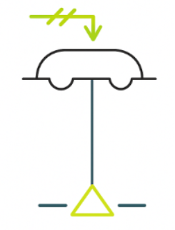
(i) Air-to-Open (Fail-Closed) Control Valve
In an Air-to-Open control valve, the actuator requires air pressure to open the valve. When the control signal increases, air pressure pushes the stem or diaphragm to lift the plug, allowing fluid to flow. If the instrument air supply fails, the spring force inside the actuator automatically pushes the valve closed. This is why the valve is also known as Fail-Closed. The diagram of air-to-open control valve is shown below.
Working Principle
- Air pressure acts against the spring force to open the valve.
- Higher signal → more air pressure → wider valve opening.
- If air signal reduces or fails → spring closes the valve to a safe closed position.
This behavior makes the valve inherently safe in situations where uncontrolled flow could be dangerous.
Advantages
- Provides fail-safe closure during emergency or air failure.
- Enhances process safety in hazardous fluid services.
- Suitable for precision throttling in high-pressure lines.
- Ensures protection of downstream equipment from overheating or over-pressurization.
Applications
This type of control valve is widely used where stopping the flow during failure is critical for safety, such as:
- Steam lines (to prevent boiler or heat exchanger damage)
- Fuel oil and natural gas supply lines (to avoid fire hazards)
- Hazardous chemical feed lines
- High-temperature or flammable process fluid systems
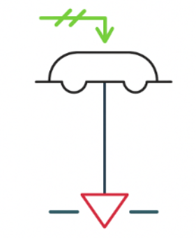
(ii) Air-to-Close (Fail-Open) Control Valve
In an Air-to-Close control valve, the actuator requires air pressure to close the valve. When the control signal increases, air pressure pushes the stem or diaphragm downward, forcing the plug into its seat and restricting fluid flow. If the instrument air supply fails, the spring force inside the actuator automatically pushes the valve open. Therefore, this valve is also known as Fail-Open. The diagram of air-to-close control valve is shown below.
Working Principle
- Air pressure acts against the spring force to close the valve.
- Higher signal → more air pressure → tighter valve closure.
- If the air signal reduces or fails → the spring opens the valve to a safe open position.
- This action ensures that fluid continues flowing when air pressure is lost.
This behavior is essential where stopping the flow could lead to equipment damage or unsafe conditions.
Advantages
- Provides fail-safe opening during air failure to maintain necessary process flow.
- Prevents overheating, pressure buildup, and equipment damage.
- Ensures continuous lubrication or cooling flow in critical systems.
- Enhances reliability in processes where flow interruption is dangerous.
Applications
This type of control valve is commonly used where uninterrupted flow is crucial for safe operation, such as:
- Cooling water supply lines (to prevent overheating of turbines, compressors, heat exchangers)
- Lubrication oil lines (ensures continuous lubrication of mechanical equipment)
- Reactor and process circulation lines (avoids pressure rise or chemical degradation)
- Air handling and ventilation safety systems
Typical in power plants, petrochemical units, refineries, and heavy machinery cooling systems.
Importance of Fail-Safe Action
The choice between fail-open and fail-closed types control valves depends on:
- Process safety requirements
- Nature of the fluid
- Consequences of flow stoppage
This classification is extremely important for plant safety and should never be ignored during design.
2. Types of Control Valves Based on Number of Plugs
Control valves are also classified based on the number of plugs used for regulating flow. In this category, there are three main types of control valves.
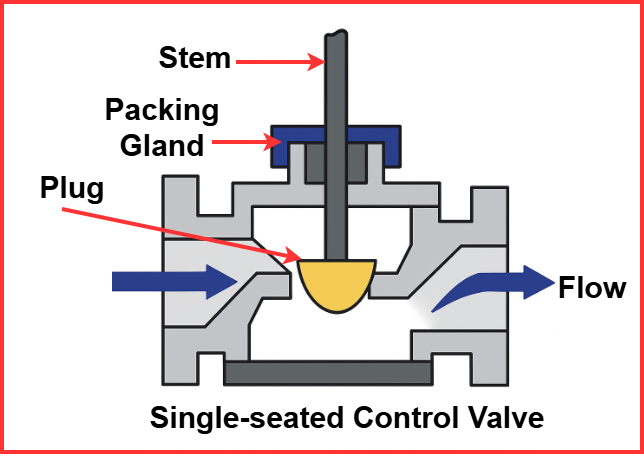
(i) Single-Seated Control Valve
A Single-Seated Control Valve consists of one valve plug and one seat. When actuated, the plug moves up or down against the seat to regulate the flow of fluid through the valve. Due to its single seating surface, this valve provides excellent shut-off capability, making it suitable for applications requiring precise control and minimal leakage.
Working Principle
- The actuator moves the valve plug against the seat to throttle the flow.
- A single seating surface provides tight contact, enabling near-zero leakage.
- Because there is no balancing plug, the actuator must overcome full process pressure, requiring higher force, especially at high differential pressures.
This configuration ensures accurate flow modulation, but may need a more powerful actuator in high-pressure systems.
Advantages
- Excellent sealing performance → capable of zero or near-zero leakage.
- High control accuracy, making it suitable for fine throttling applications.
- Simple internal structure → easy to maintain and overhaul.
- Ideal for fluids that require precise flow regulation.
Disadvantages
- Requires higher actuator force to overcome pressure differential across the valve.
- Not recommended for very large flow rate systems, as actuator size becomes impractical.
- May generate higher noise and vibration in high-pressure drop applications.
Applications
Single-Seated Control Valves are ideal where tight shut-off and precise control are essential, such as:
- Chemical dosing and feed control systems
- Precision control loops in process industries
- Low to medium flow rate pipelines
- Metering and fine-throttling operations in pharmaceutical, food processing, and specialty chemical plants
(ii) Double-Seated Control Valve
A Double-Seated Control Valve contains two valve plugs and two seats arranged in such a way that the fluid forces acting on the plugs partially balance each other. This balanced force design significantly reduces the actuator effort required to move the valve, making it suitable for handling higher flow rates with moderate actuator size.
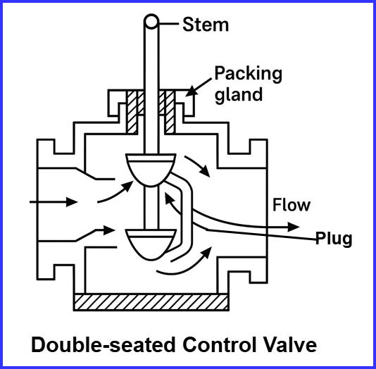
Working Principle
- The valve has two plugs moving simultaneously against two seats.
- The opposing fluid forces acting on each plug counterbalance each other, reducing the net force on the actuator.
- This allows the valve to control large flow rates without needing a large actuator.
- However, due to two seating surfaces, achieving zero leakage is difficult, and slight internal leakage is common.
This design prioritizes flow capacity and reduced actuator load over perfect shut-off.
Advantages
- Lower actuator force requirement due to balanced plug design.
- Capable of handling higher flow capacities, making it suitable for large pipelines.
- More economical for applications requiring high flow regulation.
- Reduced mechanical stress on actuator and valve components.
Disadvantages
- Tight shut-off is not possible — some internal leakage is expected.
- Slightly more complex internal design, requiring careful maintenance.
- Not suitable for hazardous or toxic fluids where zero leakage is essential.
- May produce noise under high-pressure conditions.
Applications
Double-Seated Control Valves are commonly used where high flow capacity is needed, and slight leakage is acceptable:
- Large process lines in refineries and petrochemical plants
- Steam distribution networks
- Cooling water and utility systems
- General-purpose flow control in power plants
- Non-hazardous fluid transport lines in process industries
When to Choose Which Valve?
| Requirement | Choose This Valve | Reason |
| Tight shut-off required | Single-seated | Can fully close |
| High flow rate | Double-seated | Requires less actuator force |
| Precision control | Single-seated | Higher accuracy |
| Leakage acceptable | Double-seated | Provides economical operation |
3. Types of Control Valves Based on Flow Characteristics
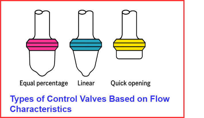
The flow characteristic describes how the flow rate changes when the valve opening is gradually adjusted.
(i) Linear Flow Characteristic
In a Linear Flow Characteristic control valve, the flow rate changes in direct proportion to the valve stem travel. This means that if the valve opens 40%, the flow also increases to approximately 40% of its maximum capacity. The relationship between valve opening and flow is straight-line and predictable, making it suitable for processes requiring precise and steady control.
Working Principle
- The valve plug is shaped so that each equal increment of stem movement results in an equal increment of flow change.
- Flow increases linearly with valve travel:
- 10% opening → ~10% flow
- 50% opening → ~50% flow
- 90% opening → ~90% flow
- Position feedback signals from the controller maintain this proportional flow output.
This predictable behavior ensures stable and smooth control, especially when the system operates over a narrow flow range.
Advantages
- Simple and predictable control response.
- Ideal for systems where valve position directly reflects flow rate.
- Provides high accuracy in mid-range valve travel.
- Reduces tuning complexity for linear control loops.
- Preferred where process dynamics are stable and steady.
Disadvantages
- At very low valve openings, control resolution decreases.
- Not suitable for systems where load changes frequently.
- Can produce oversized flow rates at higher travel if system pressure varies.
- Less effective in processes requiring exponential or gradual flow changes.
Applications
Linear Flow Characteristic valves are commonly used in systems where flow regulation must be direct and proportional, such as:
- Chemical feed and mixing operations
- Liquid level control loops in tanks and reactors
- Heat exchanger bypass control
- General throttling service in process lines
- Industrial automation loops requiring steady and predictable response
(ii) Equal Percentage Flow Characteristic
In an Equal Percentage Flow Characteristic control valve, the flow rate increases exponentially with valve stem movement. This means that small changes in valve opening at lower positions produce very small changes in flow, while larger openings result in increasingly larger flow increments. This non-linear response makes the valve ideal for systems where pressure or load conditions change frequently, ensuring stable and efficient control throughout the operating range.
Working Principle
- At low valve openings, the flow changes slowly and smoothly.
- As the valve opens further, the flow rate increases more rapidly for each additional movement.
- The flow relationship is non-linear and exponential, matching the dynamic behavior of many industrial processes.
- This characteristic helps to offset pressure fluctuations in pipelines, maintaining accurate control.
Advantages
- Provides precise control at low flow ranges, reducing the risk of overshoot.
- Handles wide variations in system load more effectively than linear valves.
- Improves process stability where operating conditions change throughout production.
- Reduces valve hunting and instability in sensitive control loops.
- Enhances energy efficiency and operational performance.
Disadvantages
- Flow adjustment can seem slow near the closed position.
- Requires proper sizing and tuning to achieve its full performance benefits.
- More complex internal plug design compared to linear valves.
Applications
- Used in steam distribution systems where pressure variations are common.
- Ideal for boiler feedwater control, matching variable steam demand.
- Applied in temperature control loops in heaters, reactors, and heat exchangers.
- Suitable for chemical reactors where process conditions change throughout operation.
- Common in HVAC heating and cooling circuits with fluctuating load conditions.
- Used in reboilers and evaporators for smooth and stable vapor flow control.
- Widely preferred in power plants, refineries, and petrochemical industries due to their adaptability in dynamic processes.
(iii) Quick Opening Flow Characteristic
In a Quick Opening Flow Characteristic control valve, the flow rate increases rapidly with a small initial movement of the valve stem. Even when the valve opens only a little, a large amount of flow passes through. Once the valve reaches a mid-opening position, additional movement results in much smaller increases in flow. This behavior makes quick opening valves ideal for on-off or emergency flow service, where fast flow response is more important than precise throttling.
Working Principle
- The valve plug is designed so that small changes in stem travel result in large flow changes.
- Flow increases sharply as the valve just starts to open.
- After approximately 40–50% opening, the rate of flow increase becomes smaller.
- This characteristic is intended for rapid flow availability, not precise modulation.
This working behavior suits applications requiring immediate system response, particularly in safety and emergency control operations.
Advantages
- Provides instant high flow with minimal valve travel.
- Ideal for quick start or quick shut-off requirements.
- Enhances safety response in critical conditions.
- Protects equipment by allowing fast pressure relief or cooling.
- Simple and reliable for on-off control situations.
Disadvantages
- Not suitable for precise flow control or continuous throttling duty.
- May lead to unstable control if used in modulating loops.
- Limited use in normal regulating applications; best suited for specific emergency functions.
Applications
Quick Opening Flow Characteristic valves are commonly used where fast flow response is essential, such as:
- Emergency shutdown (ESD) systems
- Pressure relief and blowdown lines
- Venting and draining systems
- Fuel gas shut-off and safety isolation valves
- Emergency cooling circuits and bypass lines
- On-off service lines in process and utility systems
Common Valve Body Types in Control Valves
Control valves also differ based on body design and motion type.
| Type of Valve | Working Principle | Features | Typical Use |
| Globe Valve | Linear motion plug movement | High accuracy | Process control loops |
| Ball Valve | Rotational ball movement | Fast response, minimal pressure drop | On/Off & modulating services |
| Butterfly Valve | Rotating disk controls flow | Lightweight, economical | Large pipe diameters |
| Diaphragm Valve | Flexible diaphragm seals passage | Good for corrosive fluids | Chemical & pharmaceutical |
| Plug Valve | Cylindrical plug rotates to open/close | Simple operation | Oil and gas pipelines |
Applications of Control Valves
Control valves are used in nearly every industrial process, including:
- Oil & Gas Refineries – flow and pressure control
- Chemical Plants – temperature and reaction control
- Power Plants – boiler steam and feedwater control
- HVAC Systems – chilled water and air handling
- Water Treatment Plants – chemical dosing and flow balancing
- Food & Pharma – hygienic flow control applications
They help maintain:
- Product quality
- Safe operating conditions
- Stable energy consumption
Factors to Consider When Selecting a Control Valve
Choosing the correct valve requires analyzing:
| Parameter | Consideration |
| Nature of fluid | Corrosive, clean, slurry, viscous |
| Flow rate & pressure | Determines valve size |
| Required shut-off capability | Single vs double seated |
| Safety position | Fail-open or fail-closed |
| Control accuracy | Valve characteristic curve |
| Maintenance & cost | Lifecycle performance |
A properly selected control valve increases system efficiency and reduces downtime.
Conclusion
A clear understanding of the types of control valves is important when selecting the right valve for any process control task. Valves can be designed as air-to-open or air-to-close, providing the necessary fail-safe response during loss of instrument air.
Likewise, single-seated valves are preferred where a tight shut-off is required, whereas double-seated valves are suitable for applications involving higher flow capacity with reduced actuator force. The choice of flow characteristics—linear, equal percentage, or quick opening—helps match the valve’s performance to the specific behavior of the process.
By choosing the appropriate control valve and maintaining it properly, industries can achieve better process efficiency, higher safety standards, and consistent product quality. Ultimately, control valves play a crucial role in ensuring smooth and reliable operation across modern industrial automation systems.
Related Articles: