In industrial automation and process control, maintaining stable and accurate operating conditions is essential. Whether it is controlling the temperature in a heat exchanger, pressure in a pipeline, level in a tank, or the flow rate in a reactor, one key device ensures this precision — the control valve. The working principle of control valve is to regulate the flow of fluids such as water, steam, gas, or chemical compounds by adjusting the opening of its internal passage. This makes it the most important final control element in any process control loop.
This article explains the working principle of control valve in a clear and practical way, along with its major parts, flow characteristics, fail-safe actions, tuning concepts, applications, and real industrial use cases.
What is Control Valve?
A control valve is a mechanical device installed in pipelines to control the flow of a fluid. By changing the opening through which the fluid passes, the valve directly influences process variables.
Control valves are commonly used to maintain:
| Controlled Parameter | Example Process |
| Flow | Feed flow to reactors |
| Pressure | Natural gas distribution |
| Level | Tank level control |
| Temperature | Steam heating systems |
Because they directly affect the process outcome, control valves are called the hands of the control system.
Working Principle of Control Valve
The working principle of control valve is based on controlling the fluid flow rate by adjusting the resistance to the flow inside the pipeline. This resistance is varied by changing the opening (or passage area) of the valve.
The valve does not work independently. It operates as part of a closed-loop control system. The process variable (such as pressure, level, or temperature) is continuously measured by a sensor, which sends the measurement to a controller. The controller compares the measured value with the setpoint (desired value). If there is any difference, the controller sends a signal to the valve actuator.
The signal is usually:
- 3–15 psi (pneumatic)
- 4–20 mA (electrical)
The actuator converts this control signal into mechanical motion. This motion is transmitted through the valve stem, which moves the valve plug, disc, or ball. As this position changes, the effective flow area within the valve either increases or decreases.
Flow Variation:
- If the valve opening increases → Resistance decreases → Flow increases
- If the valve opening decreases → Resistance increases → Flow decreases
This continuous adjustment allows the system to maintain the process variable close to the setpoint. Thus, the control valve ensures smooth, accurate, and stable process operation even under load disturbances.
Control Loop Interaction
A typical control loop contains:
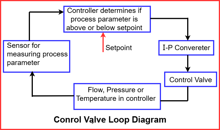
- A control valve operates as part of a closed-loop control system to maintain a process at the desired setpoint.
- The sensor first measures the process variable such as flow, pressure, level, or temperature.
- This measured value is then sent to a transmitter, which converts it into a standard pneumatic or electrical signal for communication.
- The controller receives this signal and compares the actual process value with the setpoint.
- If there is any difference (error), the controller calculates whether the flow needs to increase or decrease.
- The controller then sends a corresponding control signal to the control valve.
- The control valve adjusts its opening to either allow more or less fluid to pass.
- This adjustment influences the process, helping it return to the desired condition.
- The control valve adjusts the process, and the new process condition is fed back again, completing the loop.
- The loop continuously repeats, ensuring stable and automatic control.
This closed-loop operation ensures continuous automatic control.
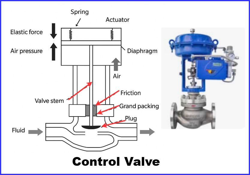
Major Parts of a Control Valve
A control valve typically consists of the following major components:
- Valve Body
- The valve body forms the main outer casing of the control valve and contains the passage through which the fluid flows.
- It must be capable of withstanding system pressure, fluid velocity, and operating temperature conditions.
- Depending on the process fluid and environment, the body is commonly made from carbon steel, stainless steel, alloy steel, or special corrosion-resistant materials.
- The body design also influences flow capacity and how easily the valve can be installed or maintained.
- Valve Trim
- The trim is the internal assembly that performs the actual control of flow.
- It includes the plug, ball, or disc, along with the seat and stem. These components adjust the flow area inside the valve.
- The geometry and profile of the trim determine the flow characteristic, how smoothly the valve modulates flow, the pressure drop, and how tight the shut-off is.
- Trim surfaces are often hardened, polished, or coated to resist wear, erosion, and cavitation.
- Actuator
- The actuator supplies the mechanical force needed to move the stem and adjust valve opening.
- Pneumatic actuators are most widely used due to quick response and reliability.
- Electric and hydraulic actuators are chosen when higher precision, remote operation, or high force is required.
- Valve Stem
- The stem connects the actuator to the valve plug/ball/disc and transmits motion accurately.
- Positioner
- The positioner ensures the valve reaches the exact opening corresponding to the control signal, improving accuracy and stability.
- Bonnet and Packing
- These components seal the area around the stem, preventing leakage and ensuring safe, long-term operation.
Summary: Parts of Control Valve
| Component | Description | Function |
| Valve Body | Main pressure-containing structure | Provides flow passage |
| Valve Trim | Plug, seat, disc, ball, cage | Determines flow characteristics |
| Actuator | Pneumatic, electric, or hydraulic | Moves the valve stem |
| Valve Stem | Connects trim to actuator | Transmits motion |
| Positioner | Feedback device | Ensures precise valve opening |
| Bonnet & Packing | Sealing assembly | Prevents leakage around stem |
The trim design largely determines how the valve throttles flow.
Types of Actuators
| Actuator Type | Features | Best Used In |
| Pneumatic | Simple, reliable, safe | Refineries, chemical plants |
| Electric | Accurate positioning, no air required | Remote or clean environments |
| Hydraulic | Very high force capability | Pipelines, high-pressure systems |
Flow Characteristics (Valve Trim Profiles)
Flow characteristics describe how the flow rate changes in response to the valve opening. These characteristics are determined by the shape and design of the valve trim.
- Linear Characteristic:
Flow increases directly proportional to stem travel. Every equal movement of the valve stem results in an equal change in flow rate. This type is commonly used in level control and systems where process gain remains fairly constant. - Equal Percentage Characteristic:
Flow increases slowly at first, then rapidly at higher openings. Each increment in valve travel results in a percentage increase in flow. Ideal for temperature and pressure control where system gain varies. - Quick Opening Characteristic:
Produces maximum flow with a small initial opening, making it suitable for on/off control, safety relief, and emergency shutdown operations.
Control Valve Actions and Signal Direction
Control valves operate based on how they respond to changes in air signal.
- Air-to-Open (ATO):
- Valve opens when the air signal increases.
- In case of air failure, the valve closes (Fail-Close action).
- Used where the safe condition is to stop fluid flow.
- Air-to-Close (ATC):
- Valve closes when the air signal increases.
- If air pressure is lost, the valve opens (Fail-Open action).
- Preferred where continuous flow is required for safety.
Fail-Safe Modes
Control valves are designed with specific fail-safe modes to ensure safe operation during air supply loss, power failure, or signal interruption. The selected fail mode depends on the process requirement and safety philosophy of the plant.
- Fail-Open (FO)
In this mode, the valve automatically opens when the air or power signal is lost. This ensures that the process fluid continues to flow. It is commonly used in cooling water lines, emergency quench systems, and other safety-critical loops where stopping flow could cause overheating or equipment damage. - Fail-Close (FC)
Here, the valve automatically closes on failure. This mode is used for fuel, steam, gas, or chemical injection lines, where continued flow during failure could create a fire, explosion, or overreaction hazard. - Fail-in-Place (FIP)
The valve remains in its last operating position. This is used in critical stability systems, where sudden valve movement might destabilize the process.
Control Valve Tuning
Control valve performance relies on proper PID tuning to ensure accurate, stable, and responsive process control across varying load conditions.
- P (Proportional)
- Controls the strength of correction based on the size of the error.
- Higher proportional gain increases responsiveness but may cause oscillations if too high, requiring careful adjustment.
- I (Integral)
- Eliminates steady-state error by continuously adjusting the valve position.
- Excessive integral action can slow response, cause overshoot, or create hunting if not balanced.
- D (Derivative)
- Predicts future changes by responding to the rate of error change.
- Helps stabilize the system and reduce overshoot but is sensitive to signal noise and requires proper filtering.
Common Problems and Solutions
| Issue | Probable Cause | Solution |
| Hunting / Oscillation | Valve oversized or tuning poor | Re-size or tune controller |
| Valve Not Responding | Air leakage or faulty positioner | Inspect actuator & air supply |
| Leakage through Valve | Worn trim | Replace trim components |
| Sticking (Stiction) | Tight packing or contamination | Lubricate or clean valve |
Real Industrial Application Example
In a steam heating system:
- Temperature sensor measures product temperature.
- Controller compares it with setpoint.
- Control valve modulates steam flow.
- Temperature remains stable.
If the valve is sticky → temperature fluctuates → product quality drops.
Advantages of Control Valves
- Enables precise process control
- Improves product quality
- Enhances safety and reliability
- Supports automation and efficiency
- Reduces raw material and energy wastage
Conclusion
The working principle of control valve revolves around modulating the flow passage to regulate process variables. By responding to controller signals, the valve continuously adjusts fluid flow to maintain stability. Understanding valve construction, flow characteristics, fail-safe modes, and tuning is essential for every instrumentation, chemical, and mechanical engineer.
Control valves are the heart of industrial automation, ensuring processes operate safely, efficiently, and reliably.
Related Articles: