A Magnehelic gauge is a mechanical instrument used to measure small pressure differences between two points in an air or gas system. It is commonly installed in HVAC systems, ventilation ducts, industrial plants, and cleanrooms to monitor airflow conditions and filter performance. Understanding the Magnehelic gauge working principle, installation procedure, and readings helps ensure reliable pressure monitoring and timely maintenance.
What Is a Magnehelic Gauge?
A Magnehelic gauge is a differential pressure measuring instrument that displays the pressure difference between its high-pressure and low-pressure connections. It is particularly suitable for applications where small pressure variations must be measured clearly and conveniently.
The instrument uses a diaphragm or other pressure-responsive sensing element, depending on its design, to detect the pressure difference. A mechanical and magnetic movement transfers this response to a pointer, which indicates the measured value on a calibrated dial.
The gauge does not require an external electrical power supply for its basic mechanical operation. Pressure readings are commonly expressed in inches of water column (in. w.c.), millimetres of water column (mmH₂O), or pascals (Pa), depending on the instrument’s scale.
Magnehelic Gauge Purpose
The primary purpose of a Magnehelic gauge is to monitor differential pressure and identify changes in the operating condition of equipment or ventilation systems.
Its main uses include:
- Air filter monitoring: Identifies increasing pressure drop as dust accumulates on filter media.
- Airflow monitoring: Helps assess ventilation and air-handling system performance.
- Cleanroom pressure control: Checks pressure differences between rooms and surrounding areas.
- Duct pressure measurement: Monitors static pressure in ventilation and air distribution systems.
- Fan and blower monitoring: Measures pressure differences across equipment and associated components.
- Industrial process monitoring: Measures low differential pressures in compatible air and gas applications.
For example, if a filter becomes clogged, the pressure difference across it generally increases at a comparable airflow rate. The gauge helps maintenance personnel identify this change and determine when the filter requires inspection or replacement.
Magnehelic Gauge Working Principle
The Magnehelic gauge working principle is based on the mechanical response of a sensing element to the difference between two applied pressures.
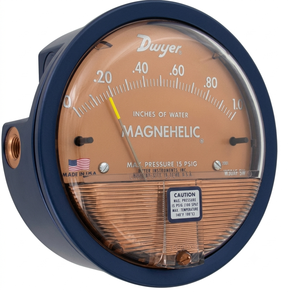
The instrument operates through the following steps:
- Pressure application: The higher pressure is connected to the high-pressure port, marked
+, while the lower pressure is connected to the low-pressure port, marked−. - Differential pressure develops: The pressure difference acts on the sensing mechanism inside the gauge.
- Sensing element responds: The diaphragm or equivalent mechanism moves according to the applied differential pressure.
- Magnetic movement transfers motion: The internal mechanism converts the sensing element’s response into pointer movement without requiring a conventional direct mechanical linkage through the pressure boundary.
- Reading appears on the dial: The pointer indicates the differential pressure on the calibrated scale.
The pressure difference is calculated as:
Where:
- = Differential pressure
- = Pressure at the high-pressure connection
- = Pressure at the low-pressure connection
If the high-pressure port receives 500 Pa and the low-pressure port receives 300 Pa, the differential pressure is:
Therefore, the gauge should indicate a differential pressure of 200 Pa, provided the selected range and connection arrangement are suitable.
Depending on its design and scale, a Magnehelic gauge may measure positive differential pressure, negative pressure relative to a reference, or both directions.
Magnehelic Gauge Installation
Correct Magnehelic gauge installation is essential for obtaining dependable readings and avoiding damage to the sensing mechanism.
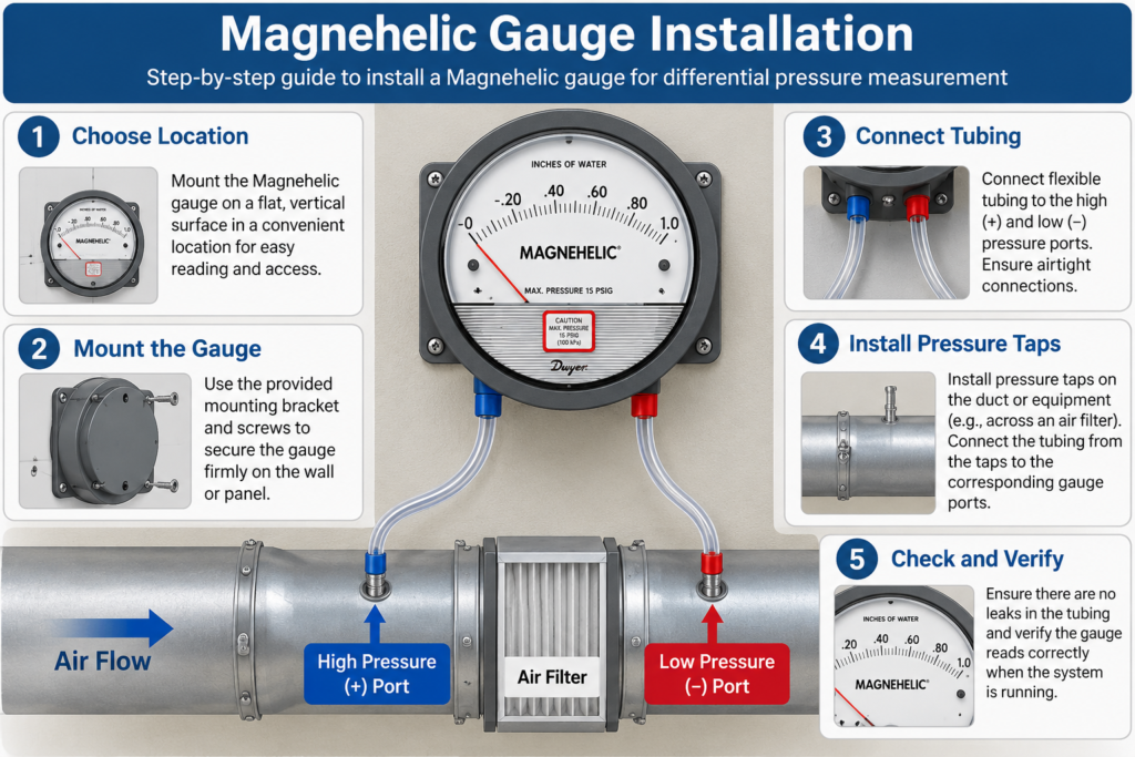
Follow these installation steps:
- Select the correct range: Choose a gauge whose measuring range covers the expected differential pressure. A suitable range improves readability and helps prevent over-ranging.
- Choose the mounting location: Install the instrument where the dial is easy to read and the gauge is protected from excessive vibration, moisture, and temperature outside its specified limits.
- Mount the instrument: Secure the gauge using the manufacturer’s recommended mounting arrangement. Keep it in the specified orientation, as some models require a particular position for accurate readings.
- Connect the pressure tubing: Connect the higher-pressure line to the
+port and the lower-pressure line to the−port. For filter monitoring, the connections are generally taken from the upstream and downstream sides of the filter. - Check the tubing: Inspect the lines and fittings for leaks, blockages, loose connections, or kinks.
- Verify the zero reading: With both ports exposed to the same pressure, confirm that the pointer returns to zero, following the manufacturer’s instructions.
- Check the operating reading: Start the system and compare the indicated differential pressure with the expected operating value.
Important: Do not expose the gauge to pressure beyond its specified limits. The allowable overpressure depends on the particular model and its construction. Built-in protection, where provided, should not be treated as permission to exceed the manufacturer’s ratings.
Magnehelic Gauge Readings Chart
A Magnehelic gauge readings chart helps users interpret the dial and understand the relationship between pressure units.
The actual dial markings vary with the selected model and measuring range. The following table provides common pressure conversions for interpreting readings.
| Pressure in Pa | Pressure in mmH₂O | Pressure in in. w.c. |
| 25 Pa | 2.55 | 0.10 |
| 50 Pa | 5.10 | 0.20 |
| 100 Pa | 10.20 | 0.40 |
| 125 Pa | 12.75 | 0.50 |
| 250 Pa | 25.49 | 1.00 |
| 500 Pa | 50.99 | 2.01 |
| 1,000 Pa | 101.97 | 4.02 |
These are approximate unit conversions, not universal gauge scale markings. Always read the units and range printed on the installed instrument.
How to Read a Magnehelic Gauge
To obtain the correct reading:
- Identify the unit printed on the dial.
- Observe the pointer position against the calibrated scale.
- Record the indicated differential pressure.
- Compare the reading with the normal operating range specified for the equipment.
- Investigate an unexpected increase or decrease before adjusting the system.
For example, a reading of 0.8 in. w.c. represents a differential pressure of approximately 199 Pa. Whether this is normal depends on the equipment, airflow, and manufacturer’s operating limits.
Magnehelic Gauge vs Manometer
A Magnehelic gauge and a manometer both measure pressure, but they use different methods of indication. The appropriate choice depends on the application, required accuracy, measuring range, and installation conditions.
| Feature | Magnehelic Gauge | Liquid Manometer |
| Measuring principle | Mechanical sensing and pointer indication | Liquid-column displacement |
| Display | Calibrated dial | Difference in liquid levels |
| Power requirement | No external power for basic operation | No external power for a conventional liquid manometer |
| Portability | Convenient for permanent panel or wall mounting | Depends on the design |
| Reading method | Direct pointer reading | Read liquid-level difference |
| Maintenance | Generally low; periodic verification may be required | May require checking liquid level, condition, and leakage |
| Typical application | Continuous differential pressure monitoring | Reference measurements, laboratory work, and pressure checks |
A Magnehelic gauge is often preferred for continuous monitoring because its dial can be read quickly without measuring a liquid column. A manometer can be useful for reference measurements, particularly when its resolution and measurement range suit the task.
However, neither instrument is automatically more accurate in every situation. Accuracy depends on the particular model, calibration, measurement range, installation, and operating conditions.
Advantages of a Magnehelic Gauge
The main advantages of this instrument include:
- Easy-to-read indication: The pointer provides a direct visual representation of differential pressure.
- No external power supply: The basic mechanical design operates without electricity.
- Suitable for low pressures: Available models measure small pressure differences in ventilation and process systems.
- Simple installation: The instrument can be connected to pressure taps using suitable tubing and fittings.
- Low maintenance requirements: The absence of complex electronic components can simplify routine servicing.
- Continuous monitoring: Operators can observe pressure changes during normal system operation.
Actual performance, accuracy, environmental suitability, and maintenance requirements depend on the specific model.
Limitations of a Magnehelic Gauge
Despite its advantages, a Magnehelic gauge has several limitations:
- It must be selected with an appropriate pressure range.
- Incorrect mounting or zero adjustment can affect the reading.
- Leaking, blocked, or incorrectly connected tubing can cause misleading indications.
- Excessive pressure, vibration, contamination, or unsuitable environmental conditions may damage the instrument or affect performance.
- The pointer provides a local indication unless the installation includes a separate monitoring or transmission arrangement.
For applications requiring data logging, remote monitoring, or automated control, a suitable electronic differential pressure transmitter may be more appropriate.
Maintenance and Calibration
Periodic inspection helps maintain measurement reliability. The inspection interval should be based on the manufacturer’s recommendations, operating conditions, required measurement accuracy, and the importance of the application.
Routine checks may include:
- Inspecting the gauge body, dial, mounting, and pressure connections.
- Checking tubing for leaks, obstructions, and deterioration.
- Confirming that the pointer returns to zero when both ports are at equal pressure.
- Comparing readings with a suitable calibrated reference instrument.
- Checking the indication at several points across the working range when required.
- Recording any errors and arranging adjustment, repair, or replacement according to the manufacturer’s procedure.
For formal calibration, use a suitable reference pressure source or differential pressure calibrator and follow the applicable procedure for the instrument model. A zero check alone does not establish accuracy across the full measuring range.
Read detailed artcile on: Magnehelic Gauge Calibration
Conclusion
A Magnehelic gauge is a practical instrument for measuring and monitoring low differential pressures in HVAC, cleanroom, ventilation, and industrial applications. Its mechanical sensing arrangement and direct dial indication make it useful for identifying changes in filter resistance, duct pressure, and other low-pressure conditions.
Understanding the Magnehelic gauge working principle, installation requirements, readings chart, and comparison with a manometer helps users select and operate the instrument correctly. Regular inspection and calibration, where required, further support reliable measurements and safe system operation.
Read Next: