A SMART transmitter is a microprocessor-based instrument that measures a process variable, such as pressure, temperature, flow, or liquid level, and converts the measurement into a usable output signal. Unlike a conventional analog transmitter, it can process measurement data digitally, store configuration information, perform diagnostic checks, and support remote configuration through a compatible communication system.
SMART transmitters are widely used in industrial automation because they provide more than a basic measurement signal. They can help instrument engineers monitor device health, adjust measuring ranges, identify faults, and improve the reliability of process control systems.
Depending on the model, a SMART transmitter may provide a conventional 4–20 mA analog output together with digital communication through protocols such as HART, or communicate through a digital fieldbus or another supported interface.
How Does a SMART Transmitter Work?
A SMART transmitter receives a physical input from a sensor and processes it using electronic signal-conditioning circuits and a microprocessor. The processed measurement is then converted into an output that can be read by a PLC, DCS, indicator, or other compatible control system.
For example, a smart pressure transmitter senses pressure in a process pipeline, calculates the corresponding pressure value, and transmits the result to the control room.
The basic working sequence is:
- Sensing: The sensing element detects the process variable and produces an electrical signal.
- Signal conditioning: Electronic circuits condition the sensor signal to make it suitable for processing.
- Analog-to-digital conversion: An ADC converts the conditioned analog signal into digital data.
- Digital processing: The microprocessor applies the configured measurement range, linearization, compensation, and other applicable calculations.
- Output generation: The transmitter produces an analog output, digital measurement data, or both, depending on its design.
- Communication and diagnostics: A compatible communication interface allows users to read configuration data, access supported diagnostic information, and adjust permitted settings.
In a typical 4–20 mA transmitter, the analog current represents the measured process variable, while a compatible digital protocol can provide additional information without requiring a separate analog signal for every parameter.
Block Diagram of a SMART Transmitter
The main functional sections of a SMART transmitter are shown below.
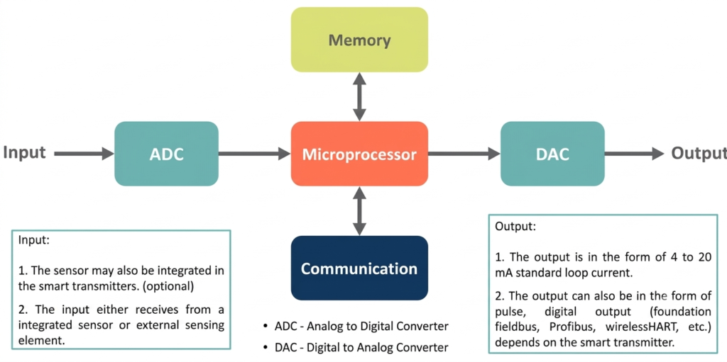
A digital communication interface connects the microprocessor to a compatible handheld communicator, configuration tool, or control system.
The major blocks perform the following functions:
- Sensor: Detects the physical process variable, such as pressure, temperature, or flow.
- Signal-conditioning circuit: Amplifies, filters, or otherwise conditions the sensor signal.
- Analog-to-digital converter (ADC): Converts the analog measurement into digital data.
- Microprocessor: Processes the measurement, applies configured calculations, and manages device functions.
- Memory: Stores firmware, measuring-range settings, identification details, calibration parameters, and supported diagnostic information.
- Digital-to-analog converter (DAC): In transmitters with an analog current output, helps generate the corresponding output signal.
- Communication interface: Enables supported digital communication with external configuration or monitoring equipment.
The exact arrangement depends on the manufacturer and transmitter model. Not every SMART transmitter uses the same hardware architecture or supports the same communication functions.
Main Components of a SMART Transmitter
1. Sensor or Transducer
The sensor is the primary element that responds to the process variable. A pressure transmitter may use a piezoresistive or capacitive sensing element, while a temperature transmitter may receive a signal from an RTD or thermocouple.
The sensor converts the physical quantity into an electrical signal that the transmitter can process.
2. Signal-Conditioning Circuit
The sensor output may be weak, nonlinear, or affected by electrical noise. The signal-conditioning circuit prepares it for accurate conversion and processing.
Depending on the design, this circuit may provide amplification, filtering, excitation, temperature compensation, and other necessary functions.
3. Analog-to-Digital Converter
The ADC converts the conditioned analog sensor signal into a digital representation. The microprocessor uses this data to calculate the process measurement.
ADC resolution, conversion performance, sensor characteristics, and signal-conditioning quality all influence the overall measurement performance.
4. Microprocessor
The microprocessor is the central processing unit of the transmitter. It executes the device firmware and performs calculations required to convert sensor data into engineering units or an output signal.
Depending on the model, its functions may include linearization, compensation, range adjustment, configuration management, and diagnostic processing.
5. Memory
Memory stores the transmitter’s operating program and relevant device data. This can include the configured tag, measuring range, engineering units, calibration parameters, and diagnostic records.
The information available and the way it is stored vary by manufacturer and model.
6. Output Circuit
The output section communicates the measured value to the connected control system. In a conventional 4–20 mA SMART transmitter, a DAC and current-control circuit may generate the analog output.
Other models may use a digital output interface or fieldbus connection. The output arrangement depends on the selected transmitter.
7. Digital Communication Interface
The communication interface enables authorized users or compatible systems to read device information and change supported settings. Common examples include HART and digital fieldbus interfaces.
This capability makes it possible to configure and troubleshoot instruments without relying exclusively on the analog output signal.
SMART Transmitter Output Signal and 4–20 mA Calculation
Many SMART transmitters use a 4–20 mA current loop to represent the measured process variable. The lower range value (LRV) corresponds to 4 mA, while the upper range value (URV) corresponds to 20 mA.
For a linear measurement, the output current is calculated as:
Where:
- = output current in mA
- = measured process variable
- = lower range value
- = upper range value
Example:
Suppose a pressure transmitter has a measuring range of 0 to 10 bar. If the measured pressure is 6 bar, the output current is:
Therefore, a pressure of 6 bar corresponds to an output of 13.6 mA, assuming a linear 0–10 bar configuration and normal operation.
The same calculation applies to other linear process variables when the transmitter is configured for a 4–20 mA output. For differential-pressure flow measurement, the relationship between differential pressure and flow may require square-root extraction, depending on the transmitter configuration and control-system arrangement.
Communication Protocols Used in SMART Transmitters
SMART transmitters may support different communication methods. The available protocol depends on the instrument design and the plant’s automation system.
| Protocol or interface | Main purpose |
| HART | Combines a 4–20 mA analog signal with digital communication over the same current loop in conventional HART installations |
| FOUNDATION Fieldbus | Supports digital communication and control functions over a fieldbus network |
| PROFIBUS PA | Provides digital communication for process automation instrumentation |
| Wireless communication | Available on selected transmitters for remote monitoring and configuration using a supported wireless technology |
HART Communication
HART stands for Highway Addressable Remote Transducer. It is commonly used with SMART transmitters that provide a 4–20 mA output.
In a typical HART installation, a digital communication signal is superimposed on the analog current signal. This allows the control system to continue using the analog measurement while a compatible communicator accesses additional device information.
Depending on the transmitter, users may be able to read the process value, change the measuring range, inspect diagnostics, or configure other supported parameters.
Important distinction: SMART describes the transmitter’s electronic and processing capabilities, whereas HART is a communication protocol. They are related concepts, but they do not mean the same thing. Not every SMART transmitter uses HART, and not every smart device supports every communication feature.
Advantages of SMART Transmitters
SMART transmitters offer several benefits compared with basic analog transmitters.
1. Improved Measurement Performance
Digital processing can support linearization, compensation, and correction of certain measurement errors. Actual accuracy depends on the sensor, transmitter design, calibration, operating conditions, and installation.
2. Remote Configuration
Compatible communication tools allow engineers to change supported parameters, such as the measuring range, engineering units, tag, or damping settings, without making every adjustment directly at the instrument.
3. Self-Diagnostics
Many models can identify certain internal faults, sensor problems, or abnormal operating conditions. Diagnostic capability varies by device and does not replace all physical inspections or calibration checks.
4. Automatic Compensation
Some transmitters compensate for temperature effects, nonlinear sensor response, or other known influences. The available compensation functions depend on the sensing technology and device design.
5. Flexible Ranging
A transmitter may support multiple measuring ranges within its specified limits. This allows the range to be reconfigured when the process requirements change, provided the sensor and transmitter remain suitable for the application.
6. Better Maintenance Planning
Device diagnostics and stored information can help maintenance teams identify developing problems and prioritize inspections. This may reduce unnecessary maintenance, although it does not eliminate the need for periodic verification.
7. Additional Process Information
Certain models can provide secondary measurements, sensor status, device temperature, or other diagnostic data. Multi-variable transmitters can calculate additional process quantities when the required sensors and algorithms are available.
8. Reduced Spare-Instrument Inventory
Where transmitters share compatible hardware and sufficient measuring-range capability, a configurable spare may replace more than one instrument type. This depends on process compatibility, connection requirements, approvals, and range limitations.
9. Integration With Automation Systems
Supported communication interfaces help integrate field devices with PLCs, DCSs, asset-management systems, and other industrial monitoring tools.
10. Improved Long-Term Stability
Digital compensation and device diagnostics may help maintain measurement performance and identify drift. However, smart electronics alone do not guarantee long-term stability or eliminate recalibration requirements.
Disadvantages and Limitations of SMART Transmitters
Despite their benefits, SMART transmitters have some limitations.
- Higher initial cost: They may cost more than simpler analog instruments because of their electronic processing and communication capabilities.
- Configuration complexity: Correct setup requires knowledge of measuring ranges, output settings, communication protocols, and device parameters.
- Dependence on compatible tools: Access to advanced functions may require a suitable communicator, software, interface, or device-description file.
- Power and wiring requirements: The installation must meet the transmitter’s power-supply, loop-resistance, grounding, and communication requirements.
- Calibration is still necessary: Digital compensation and self-diagnostics do not automatically prove that the complete measurement loop remains accurate.
- Protocol compatibility: Not every transmitter is compatible with every communication network or asset-management system.
- Maintenance expertise: Technicians may need additional training to interpret diagnostic messages and configure advanced features.
SMART Transmitter vs Conventional Analog Transmitter
| Feature | SMART transmitter | Conventional analog transmitter |
| Signal processing | Uses a microprocessor for digital processing | Generally relies on simpler electronic processing |
| Output | May provide analog and digital outputs | Commonly provides an analog output |
| Configuration | Often supports remote configuration | Frequently requires local adjustment or manual calibration procedures |
| Diagnostics | May provide built-in diagnostic information | Usually offers more limited diagnostic capabilities |
| Range adjustment | Often configurable within specified limits | Depends on the transmitter design |
| Compensation | May support digital linearization and compensation | Depends on the electronic design |
| Maintenance | Diagnostics can assist troubleshooting | May require more direct testing to identify some faults |
| Cost | Generally higher | Often lower |
| Communication | Supports one or more compatible interfaces, depending on the model | Typically limited to its analog output |
Applications of SMART Transmitters
SMART transmitters are used in process industries where reliable measurements and efficient instrument management are important.
- Pressure measurement: Monitoring pipeline pressure, vessel pressure, and filter differential pressure.
- Temperature measurement: Converting RTD or thermocouple signals into standardized outputs.
- Flow measurement: Transmitting flow-related measurements from differential-pressure, magnetic, vortex, or other compatible flow-measuring systems.
- Level measurement: Monitoring liquid levels in tanks, vessels, and process equipment.
- Power plants: Monitoring steam, water, pressure, temperature, and auxiliary process conditions.
- Cement plants: Monitoring pressure, differential pressure, temperature, and other variables in kilns, mills, filters, and material-handling systems.
- Chemical and pharmaceutical industries: Monitoring process variables and supporting instrument diagnostics.
- Water and wastewater treatment: Measuring pressure, flow, and level in treatment and distribution systems.
- Oil and gas facilities: Supporting process monitoring, measurement, and equipment diagnostics.
The specific transmitter type must be selected according to the process medium, measurement range, environmental conditions, required accuracy, hazardous-area classification, and communication requirements.
SMART Transmitter Calibration and Maintenance
Although a SMART transmitter may include diagnostic and compensation functions, its measurement accuracy must still be verified according to the instrument’s application and maintenance procedure.
A typical verification or calibration activity includes:
- Identify the transmitter, tag number, measuring range, output type, and communication protocol.
- Follow the approved isolation and safety procedure before disconnecting or testing the instrument.
- Connect a suitable calibrated reference source or measurement standard.
- Apply test values across the specified measuring range.
- Compare the reference input with the displayed process value and the transmitter output.
- Check the zero, span, linearity, and output response as applicable.
- Review device diagnostics and configuration settings.
- Adjust the instrument only when permitted by the maintenance procedure.
- Repeat the test after adjustment and document the results.
For a 4–20 mA transmitter, common test points include 0%, 25%, 50%, 75%, and 100% of the configured range. The appropriate test method depends on the transmitter type and whether the task is calibration, verification, or a loop test.
Calibration intervals should be based on manufacturer recommendations, process criticality, regulatory requirements, observed drift, and the plant’s maintenance strategy.
Conclusion
A SMART transmitter combines sensor technology, digital processing, memory, and communication functions to provide process measurements and additional instrument information. Compared with a basic analog transmitter, it can offer flexible configuration, diagnostics, compensation, and integration with industrial automation systems.
For reliable operation, the transmitter must be selected and configured correctly, connected to a compatible control system, and maintained according to its specifications. Smart features improve instrument management, but they do not replace sound installation practices, calibration, or routine maintenance.
Read Next:
- What is a Float Switch: Construction, Working, Types & Applications
- What is a Level Sensor?
- Level Gauges Explained: Types, Uses, and Selection Guide
- Reflex Level Gauges: Construction, Components, and Advantages
- Difference Between Continuous and Point Level Sensors
- Level Transmitter Calibration Procedure
- Magnehelic Gauge Calibration