A poppet valve is an important component in mechanical and fluid-control systems, designed to provide reliable switching between open and closed flow conditions. Its operation is commonly associated with cam-driven mechanisms in engines and actuator-based arrangements in industrial equipment. Depending on its design, it can handle different operating pressures, control requirements, and working environments.
What Is a Poppet Valve?
A poppet valve is a mechanical valve used to control the flow of gases or liquids through a passage by opening and closing an inlet or outlet port. It consists of a movable stem with a disc-shaped or mushroom-shaped head that rests against a specially designed valve seat to stop fluid flow.
Poppet valves are widely used in internal combustion engines to regulate the entry of the air-fuel mixture and the discharge of exhaust gases. They are also found in pneumatic systems, hydraulic equipment, compressors, and pressure-control applications.
The valve operates through the movement of its stem, which lifts the valve head away from its seat to allow fluid flow. When the actuating force is removed, a spring or fluid pressure pushes the valve head back against the seat, closing the passage.
Poppet valves are also known as mushroom valves because of their characteristic shape. Their simple construction, effective sealing, and quick operating response make them suitable for applications requiring reliable flow control.
Working Principle of Poppet Valve
A poppet valve works on the principle of opening and closing a fluid passage by moving a valve head away from or towards its seating surface.
In a typical engine arrangement, the camshaft controls the movement of the poppet valve. As the cam rotates, its raised portion pushes against the valve mechanism and moves the valve stem. This lifts the valve head from its seat and creates an opening through which gases can flow.
When the cam continues rotating, its raised portion moves away from the valve mechanism. The valve spring then pushes the stem and valve head back towards the seat, closing the passage.
The operating sequence is as follows:
- Closed position: The valve head rests firmly against the valve seat, preventing gas or fluid from passing through the port.
- Opening movement: An external actuating force moves the valve stem and lifts the valve head away from the seat.
- Fluid flow: The gap between the valve head and seat provides a passage for fluid or gas.
- Closing movement: When the actuating force is removed, the spring or fluid pressure returns the valve head to its original position.
- Sealing: The valve head contacts the seat and stops the flow.
The amount of valve lift determines the available flow area. Greater lift generally provides a larger opening and allows a higher flow rate, depending on the valve design and operating conditions.
Construction of Poppet Valve
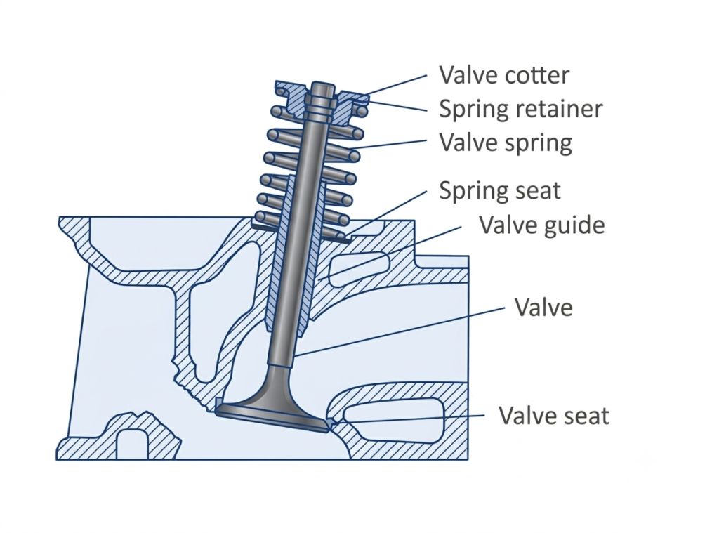
A poppet valve has a relatively simple construction. Its main components are designed to provide controlled movement and effective sealing of the fluid passage.
The important components are:
1. Valve Head
The valve head is the enlarged disc-shaped or mushroom-shaped portion of the valve. It covers the flow opening when the valve is closed. Its size and shape determine the effective flow area.
2. Valve Stem
The valve stem is a long, cylindrical portion connected to the valve head. It guides the movement of the valve and transfers the actuating force required to open or close the passage.
3. Valve Seat
The valve seat is the specially machined surface against which the valve head rests. It provides a sealing contact and prevents leakage when the valve is closed.
4. Valve Spring
The spring returns the valve to its normally closed position after the actuating force is removed. It also maintains contact between the valve head and seat.
5. Valve Guide
The valve guide supports the stem and ensures that it moves in the correct direction without excessive lateral movement.
6. Actuating Mechanism
The actuating mechanism provides the force required to move the valve. Depending on the application, it may consist of a camshaft, solenoid, pneumatic actuator, hydraulic actuator, or manual mechanism.
Operation of Poppet Valve
The operation of a poppet valve depends on its design and the mechanism used to actuate it. In an internal combustion engine, the valve generally operates through a camshaft and spring arrangement.
During the opening stroke, the rotating cam pushes the valve mechanism and forces the stem to move. As a result, the valve head moves away from the seat, allowing gases to enter or leave the engine cylinder.
During the closing stroke, the cam releases the valve mechanism. The compressed valve spring pushes the valve stem back, bringing the valve head into contact with the seat.
The valve must maintain proper contact with its seat to prevent leakage, particularly in applications involving high pressure or temperature.
In pneumatic and hydraulic systems, the operating mechanism may be different. A solenoid or actuator can move the valve stem directly, while the return spring restores the valve to its original position.
Types of Poppet Valves
Poppet valves are classified according to the number of ports and switching positions they provide. In pneumatic and hydraulic control systems, three common configurations are 2/2-way, 3/2-way, and 4/2-way poppet valves. Each type is designed to establish or interrupt specific flow connections to control the movement of fluid and connected actuators.
2/2 Poppet Valve
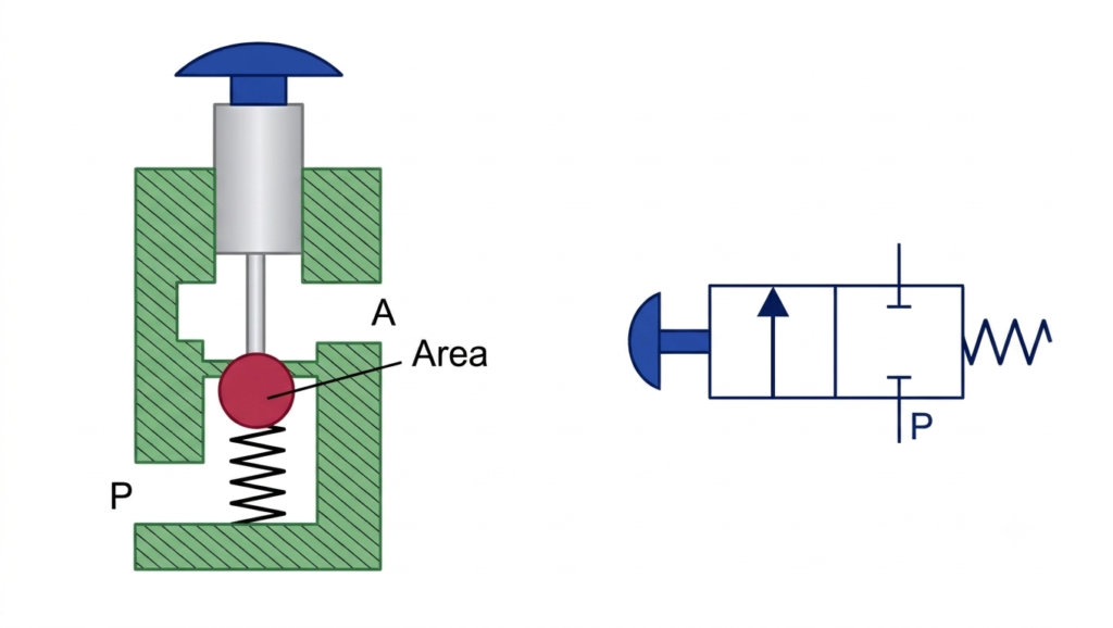
A 2/2 poppet valve has two ports and two operating positions. It is mainly used for controlling the starting and stopping of fluid flow. A normally closed arrangement is commonly used, in which the valve remains shut until an external force operates the actuator.
When the pushbutton is pressed, the internal sealing element moves away from its seat, creating a passage between the pressure port (P) and the outlet port (A). Fluid can then pass through the valve.
After releasing the pushbutton, the return spring moves the sealing element back into contact with its seat. This blocks the passage and stops the flow.
3/2 Poppet Valve
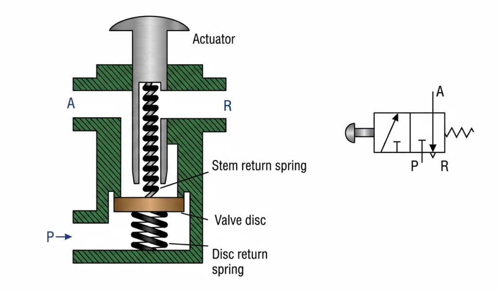
A 3/2 poppet valve contains three ports and two switching positions. Its connections generally include a pressure inlet (P), a working outlet (A), and an exhaust port (R). It is commonly used to control the supply and release of compressed air in pneumatic equipment.
In its normal position, the working outlet is connected to the exhaust port, while the pressure supply remains isolated. When the pushbutton is operated, the internal disc mechanism changes position, closes the exhaust connection, and establishes a flow path between P and A.
When the pushbutton is released, the spring-assisted mechanism restores the original position. The supply connection is closed, and the working port is connected to the exhaust.
4/2 Poppet Valve
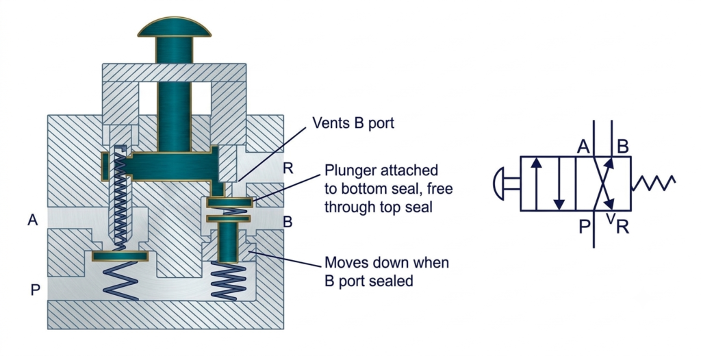
A 4/2 poppet valve consists of four ports and two switching positions. It generally has one pressure connection (P), two working connections (A and B), and one exhaust connection (R).
This valve uses an internal arrangement of stems and sealing discs to change the direction of fluid flow. In its normal position, one working port receives pressure while the other is connected to the exhaust.
When the pushbutton is pressed, the internal sealing elements operate in sequence to change the flow connections. The pressure supply is redirected to the opposite working port, while the previously pressurized port is connected to the exhaust.
Releasing the pushbutton allows the spring and fluid pressure to return the valve to its initial configuration.
This configuration is particularly useful for controlling the forward and backward movement of double-acting pneumatic cylinders.
Note: The exact switching sequence and normal flow connections depend on the internal construction of the valve. A 4/2 valve may use different sealing arrangements, so its manufacturer’s circuit symbol and operating diagram should be checked before installation.
Solenoid-Operated Poppet Valve
A solenoid-operated poppet valve uses an electromagnetic coil to control valve movement.
When electrical power is supplied to the coil, the magnetic field produces a force that moves the armature and connected valve stem. This opens or closes the flow passage depending on the valve design.
When the electrical supply is removed, a spring generally returns the valve to its original position.
These valves are used in automated machines, pneumatic control systems, and industrial process equipment.
Manufacturing and Materials of Poppet Valve
The material used for manufacturing a poppet valve depends on the operating pressure, temperature, fluid characteristics, and environmental conditions.
In internal combustion engines, the valve must withstand repeated mechanical movement, high temperatures, and combustion-related stresses.
Commonly used materials include:
- Stainless steel: Provides good corrosion resistance and mechanical strength.
- Alloy steel: Suitable for applications involving high mechanical loads and elevated temperatures.
- Heat-resistant steel: Used in exhaust valves exposed to high operating temperatures.
- Brass and bronze: Used in certain low-pressure fluid and pneumatic valve applications.
- Special alloys: Selected for demanding applications involving aggressive fluids or extreme temperatures.
The valve head and seat are machined to provide accurate contact and effective sealing. In many engine applications, the seating surfaces are manufactured with a specified angle, commonly 45 degrees, although other angles are also used depending on the engine design.
Proper surface finishing and dimensional accuracy are important because even small imperfections can cause leakage, excessive wear, or improper valve operation.
Applications of Poppet Valve
Poppet valves are used in several mechanical, automotive, and industrial applications because of their simple construction, quick operation, and reliable sealing characteristics.
1. Internal Combustion Engines
Poppet valves are widely used in petrol and diesel engines. Intake valves control the entry of air or the air-fuel mixture into the cylinder, while exhaust valves allow combustion gases to escape.
2. Pneumatic Systems
They are used to control compressed air in pneumatic circuits. Their quick switching action makes them suitable for operating pneumatic cylinders and automated equipment.
3. Hydraulic Systems
Certain poppet valve designs are used in hydraulic circuits for controlling fluid flow, isolating pressure, and preventing reverse flow.
4. Air Compressors
Poppet valves are used in some compressor designs to regulate the movement of air during suction and compression cycles.
5. Pressure Relief Systems
Spring-loaded poppet valves can be used in pressure relief arrangements. They open when the fluid pressure exceeds the specified setting and close when the pressure returns to an acceptable level.
6. Medical Equipment
Poppet-type valves are used in selected medical and pneumatic devices where controlled gas flow and reliable sealing are required. Material compatibility and cleanliness must be considered for such applications.
7. Industrial Automation
Solenoid-operated poppet valves are used in automated machinery to control the movement of pneumatic actuators and other equipment.
8. Fluid Control Equipment
They are also used in dispensing systems, fluid handling equipment, and applications requiring reliable ON/OFF flow control.
Advantages of Poppet Valves
Poppet valves offer several advantages that make them suitable for applications involving frequent switching and effective fluid control.
- Excellent sealing: The valve head makes direct contact with the seat, providing effective shut-off and reducing leakage.
- Fast operating response: Many poppet valve designs require relatively short movement to open or close the passage.
- Simple construction: Their design consists of comparatively few moving components, making maintenance easier.
- Low friction: The valve generally experiences limited sliding contact during operation, reducing friction-related wear.
- High flow capacity: Certain designs provide a large flow area when the valve is fully open.
- Self-cleaning action: The opening and closing movement, combined with fluid flow, can help dislodge some deposits from the seating region.
- Compact design: Poppet valves can be manufactured in relatively small sizes for compact equipment.
- Versatile operation: They can be operated mechanically, electrically, hydraulically, pneumatically, or manually.
- Reliable performance: Their simple operating mechanism supports dependable operation when properly designed and maintained.
Disadvantages of Poppet Valves
Despite their advantages, poppet valves also have certain limitations that should be considered during equipment selection.
- Limited flow control: Many conventional poppet valves are primarily designed for ON/OFF operation rather than precise proportional flow regulation.
- Wear of seating surfaces: Repeated contact between the valve head and seat can cause wear over time, particularly under demanding operating conditions.
- Pressure limitations: The operating pressure must remain within the valve’s design specifications.
- Spring-related limitations: The return spring may weaken, fatigue, or fail after prolonged operation.
- Noise and vibration: Rapid opening and closing can produce mechanical noise and pressure fluctuations in some systems.
- Operating force requirements: Depending on the pressure difference and valve size, considerable actuating force may be required.
- Not suitable for every vacuum application: Conventional poppet valve designs may not provide the required sealing performance in all vacuum systems. Specially designed vacuum-rated valves can overcome this limitation.
- Maintenance requirements: Deposits, damaged sealing surfaces, and worn components may require inspection and replacement.
Difference Between Normally Open and Normally Closed Poppet Valves
| Parameter | Normally Closed Valve | Normally Open Valve |
| Normal Position | Closed | Open |
| Flow Condition | Flow is stopped | Flow is allowed |
| Actuating Action | Opens the valve | Closes the valve |
| Spring Action | Maintains closed position | Maintains open position |
| Power Failure Condition | Generally remains closed | Generally remains open |
| Typical Application | Safety shut-off and flow isolation | Continuous flow applications |
Conclusion
A poppet valve is an important flow-control component used in internal combustion engines, pneumatic systems, hydraulic equipment, and industrial automation. It controls fluid movement by lifting a specially shaped valve head away from its seat and returning it to the seating surface to stop the flow.
Its simple construction, effective sealing, quick response, and versatility make it suitable for a wide range of applications. However, factors such as operating pressure, temperature, spring fatigue, seating wear, and required flow characteristics should be considered when selecting a poppet valve.
Frequently Asked Questions (FAQs)
A poppet valve is used to control the flow of gases or liquids by opening and closing a passage. It is commonly used in internal combustion engines, pneumatic systems, hydraulic circuits, and pressure-control equipment.
It is called a mushroom valve because its structure resembles a mushroom. It consists of a broad valve head connected to a narrow cylindrical stem.
A poppet valve works by moving its valve head away from the valve seat to permit fluid flow. When the actuating force is removed, a spring or fluid pressure pushes the head back against the seat to stop the flow.
The two basic types are normally closed and normally open poppet valves. A normally closed valve prevents flow in its resting position, whereas a normally open valve allows flow.
Poppet valves are manufactured using stainless steel, alloy steel, heat-resistant steel, brass, bronze, and other specialized materials depending on the operating conditions.
Read Next:
- Basics of Restriction Orifice (RO) – Types, Applications, and Standards
- Orifice Beta Ratio
- Basics of Orifice Plates
- Orifice Plate Tapping
- What is a Spool Valve? – Types, Configurations, and Applications
- Working Principle of Control Valve with Diagram, Parts & Applications
- Types of Control Valves: Definition, Classification, Working, Characteristics, and Applications
- Control Valve Positioner Working Principle