A strain gauge is an electrical sensor used to measure the deformation of a material when it is subjected to an external force. It works by detecting a change in electrical resistance as the material stretches or compresses. Strain gauges are widely used in load cells, pressure transducers, torque sensors, structural testing, and industrial measurement systems.
The strain gauge working principle is based on the relationship between mechanical strain and electrical resistance. When a strain gauge is bonded to a test specimen, it experiences nearly the same surface strain as the specimen. The resulting resistance change can be measured using a Wheatstone bridge circuit and converted into an electrical signal.
This article explains the strain gauge definition, working principle, diagram, mathematical formula, bridge circuit, temperature compensation, types, and practical applications.
What Is a Strain Gauge?
A strain gauge is a sensor that measures the relative change in the length of an object caused by an applied force. It is commonly made from a thin metallic foil or wire arranged in a grid pattern and mounted on an electrically insulating backing.
The sensor is bonded to the surface of the component being tested. When the component undergoes tension or compression, the strain gauge deforms with it, causing a small change in its electrical resistance.
The resistance change is used to determine the strain experienced by the material.
Strain is defined as the ratio of the change in length to the original length of a specimen. It is a dimensionless quantity and is commonly expressed in microstrain (µε).
For example, if a component with an original length of 100 mm elongates by 0.01 mm, its strain is:
Therefore, the strain is 100 microstrain.
A strain gauge measures strain directly. Stress can be calculated from the measured strain when the material properties and loading conditions are known.
Strain Gauge Diagram
A conventional bonded resistance strain gauge consists of a metallic sensing grid, an insulating backing, electrical terminals, and an adhesive layer that transfers deformation from the test specimen to the gauge.
The following diagram illustrates the basic construction of a strain gauge.
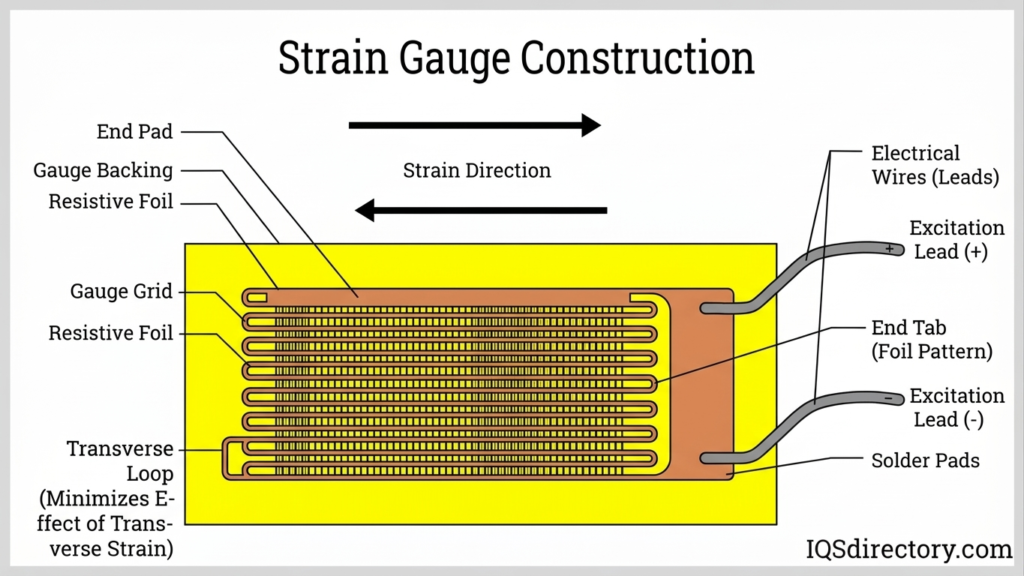
The metallic grid provides the electrical resistance that changes during deformation. Its folded pattern allows a relatively long conductor to fit into a compact area.
The gauge is designed to be most sensitive to strain along its measurement axis. Therefore, correct alignment with the expected direction of strain is important for accurate readings.
Working Principle of a Strain Gauge
The strain gauge working principle is based on the change in electrical resistance produced by mechanical deformation. When the gauge is stretched or compressed, its dimensions and, in some materials, its electrical resistivity change.
The electrical resistance of a conductor is expressed as:
Where:
- = electrical resistance in ohms
- = electrical resistivity of the material
- = length of the conductor
- = cross-sectional area of the conductor
When tensile strain is applied, the conductor generally becomes longer and its cross-sectional area decreases. These geometrical changes tend to increase its resistance. Under compressive strain, the opposite geometrical changes tend to decrease resistance.
The actual resistance response also depends on the material’s piezoresistive properties.
Step-by-step working
- Mounting: The strain gauge is bonded to the surface of the specimen using a suitable adhesive.
- Application of force: The specimen experiences tension, compression, bending, or another type of mechanical loading.
- Deformation of the gauge: The bonded sensing grid follows the deformation of the specimen.
- Resistance variation: The electrical resistance changes in response to the applied strain.
- Electrical measurement: A Wheatstone bridge detects the small resistance variation and produces a differential output voltage.
- Signal conditioning: An instrumentation amplifier and measurement system convert the bridge signal into a usable electrical reading.
- Strain calculation: The measured resistance change is converted into strain using the gauge factor and appropriate calibration.
This method enables the measurement of very small deformations that are difficult to detect using ordinary mechanical measuring instruments.
Strain Gauge Formula
The relationship between the change in resistance and the applied strain is described by the gauge factor.
The strain gauge formula is:
Rearranging the equation:
Where:
- = gauge factor
- = change in electrical resistance
- = initial resistance of the gauge
- = mechanical strain
The gauge factor indicates the sensitivity of a strain gauge to mechanical deformation.
For many conventional metallic foil strain gauges, the gauge factor is approximately 2, although the actual value depends on the particular gauge.
Example: Calculation of Strain using a Strain Gauge
A metallic strain gauge has an initial resistance of 120 Ω and a gauge factor of 2. If the resistance increases by 0.024 Ω, calculate the strain.
Given:
- Initial resistance,
- Resistance change,
- Gauge factor,
Using the formula:
Substituting the values:
Therefore:
The positive value indicates tensile strain when the resistance increase corresponds to tension for the particular gauge and installation.
Strain Gauge Bridge Circuit
A strain gauge bridge circuit is used to convert a small change in resistance into a measurable voltage. The Wheatstone bridge is the most common circuit used for this purpose.
Because the resistance change of a metallic strain gauge is generally very small, directly measuring it with an ordinary resistance meter may not provide sufficient sensitivity. A bridge circuit offers a practical way to detect these changes.
Wheatstone Bridge Diagram
A simplified Wheatstone bridge contains four resistance arms, an excitation supply, and a differential output measurement.
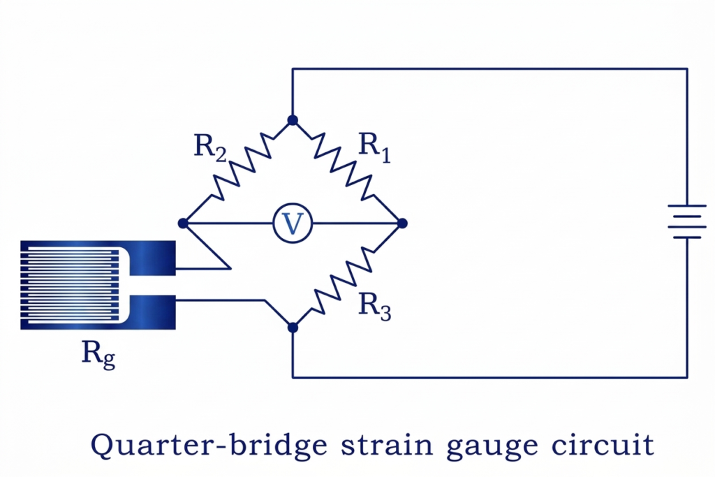
Here, represents the active strain gauge. The other resistances form the remaining bridge arms.
The output voltage is measured between the two middle junctions. The diagram is schematic; actual bridge wiring and output polarity depend on the selected configuration.
How the bridge circuit works
1. Balanced condition
When the resistance ratios of the two bridge branches are equal, the voltage at both output junctions is equal. Ideally, the differential output voltage is zero.
2. Resistance change
When mechanical strain changes the resistance of the active gauge, the bridge becomes unbalanced.
3. Output voltage generation
The difference between the junction voltages produces a small output signal. Its magnitude depends on the resistance change and excitation voltage.
4. Signal amplification
An instrumentation amplifier amplifies the bridge output so that a data acquisition system, indicator, or controller can process the measurement.
For a quarter-bridge circuit with one active gauge and three fixed completion resistors, the approximate output magnitude for a small resistance change is:
Using the gauge factor relationship:
These are small-signal approximations for a balanced bridge. The actual sign depends on the wiring and the direction of resistance change.
Types of strain gauge bridge circuits
Quarter-bridge circuit: Uses one active strain gauge and three completion resistors. It is relatively simple and economical, but can be sensitive to lead-wire resistance and temperature effects.
Half-bridge circuit: Uses two active gauges. With the correct placement and orientation, it can increase sensitivity or compensate for temperature changes and unwanted strain components.
Full-bridge circuit: Uses four active gauges. An appropriate arrangement can provide greater output sensitivity, improved temperature compensation, and better rejection of unwanted effects.
The best configuration depends on the measurement objective, mechanical loading, temperature conditions, and instrumentation requirements.
Types of Strain Gauges
Strain gauges are classified according to their sensing material, construction, and operating principle.
1. Metallic foil strain gauge
A metallic foil strain gauge uses a thin metal grid attached to an insulating carrier. Constantan and other suitable resistance alloys are commonly used.
These gauges are widely employed in industrial instrumentation because they provide good linearity, practical sensitivity, and reliable performance when properly installed.
2. Wire strain gauge
A wire strain gauge uses a fine resistance wire arranged in a suitable pattern. It operates by detecting resistance changes caused by deformation.
Wire gauges are important in the historical development of resistance strain measurement, although foil designs are widely used in modern bonded applications.
3. Semiconductor strain gauge
A semiconductor strain gauge uses the piezoresistive effect, in which mechanical stress causes a significant change in electrical resistivity.
These gauges can provide much higher sensitivity than conventional metallic gauges. However, they can be more sensitive to temperature variations and may exhibit different linearity characteristics.
4. Thin-film strain gauge
A thin-film strain gauge is formed by depositing a thin sensing material onto a suitable substrate. This construction can provide compact dimensions and good integration with specialised sensors.
Thin-film gauges are used in applications such as pressure sensing and industrial transducers.
5. Rosette strain gauge
A strain gauge rosette consists of two or three gauge grids oriented at different angles on the same carrier.
It is used when the direction of principal strain is unknown or when strain components in multiple directions must be determined. The measurements can be combined to calculate principal strains and their orientations.
Read detailed article on: Types of Strain Gauges
Temperature Compensation in Strain Gauges
Temperature variation is a major source of measurement error in strain gauge systems. A change in temperature can affect the electrical resistance of the sensing element even when no mechanical load is applied.
Temperature can also cause thermal expansion of the specimen, changes in adhesive properties, and variations in lead-wire resistance.
If these effects are not addressed, the measuring system may interpret temperature-induced resistance changes as mechanical strain.
Common temperature compensation methods include the following.
Self-temperature-compensated gauges
Certain metallic foil gauges are manufactured to minimise apparent strain over a specified temperature range when bonded to a material with a suitable thermal expansion coefficient.
The selected gauge must match the properties of the specimen as closely as practicable.
Dummy gauge method
A dummy gauge is installed in a location where it experiences approximately the same temperature as the active gauge but negligible mechanical strain.
The dummy gauge is incorporated into the bridge circuit so that similar temperature-related resistance changes in the two gauges can partially cancel.
The effectiveness of this method depends on the matching of the gauges, their thermal environments, and the bridge arrangement.
Half-bridge and full-bridge compensation
Using multiple active gauges can improve temperature rejection when the gauges are arranged so that their thermal effects cancel while their mechanical strain responses reinforce the desired output.
Lead-wire compensation
Long connecting wires introduce additional resistance that can affect measurement accuracy, especially in quarter-bridge circuits. Appropriate three-wire connections, bridge arrangements, and instrumentation can reduce this error.
For accurate measurements, the gauge excitation voltage must also remain within the manufacturer’s recommended limits. Excessive excitation can heat the sensing element and introduce measurement errors.
Factors Affecting Strain Gauge Accuracy
The accuracy of a strain gauge measurement depends on more than the sensing element alone.
- Gauge alignment: Misalignment with the intended strain direction can produce inaccurate readings.
- Surface preparation: Dirt, grease, corrosion, or an unsuitable surface finish can weaken strain transfer.
- Adhesive selection: An inappropriate adhesive or poor bonding can prevent the gauge from following the specimen accurately.
- Temperature variation: Thermal expansion and resistance changes can introduce apparent strain.
- Lead-wire resistance: Connecting wires can influence the bridge output if compensation is inadequate.
- Electrical noise: Poor shielding, grounding, and signal conditioning can affect small bridge signals.
- Excitation voltage: Excessive excitation can cause self-heating.
- Calibration: Incorrect calibration or an unsuitable gauge factor can produce systematic errors.
Following the manufacturer’s installation and calibration procedures is essential for obtaining repeatable measurements.
Applications of Strain Gauges
Strain gauges are used in mechanical engineering, electrical instrumentation, industrial automation, and structural monitoring.
1. Load cells and force measurement
Load cells use strain gauges mounted on an elastic element to measure deformation caused by an applied load. The resulting bridge output is calibrated to indicate force or weight.
Applications include weighing scales, industrial weighing systems, material testing machines, and force measurement equipment.
2. Pressure transducers
In a strain-gauge pressure transducer, pressure deforms a diaphragm or another elastic sensing element. Bonded or integrated strain gauges detect the resulting deformation and generate an electrical signal proportional to pressure over the calibrated range.
3. Torque measurement
Strain gauges can be mounted on a shaft to measure the shear strain associated with transmitted torque. Suitable gauge orientations and bridge connections allow the torque to be calculated from the measured signal.
4. Structural health monitoring
Strain gauges are used to study deformation in bridges, buildings, dams, and other civil engineering structures. Measurements help engineers evaluate structural behaviour under loading and changing environmental conditions.
5. Mechanical stress analysis
Engineers use strain gauges to evaluate strain distribution in machine components, frames, shafts, beams, and mechanical assemblies. Stress can be estimated when the material properties and stress conditions are established.
6. Automotive and aerospace engineering
Strain gauges help measure loads and deformation in vehicle components, aircraft structures, suspension systems, and test assemblies. They are valuable during product development, fatigue testing, and performance evaluation.
7. Industrial machinery
Strain gauges can be incorporated into torque sensors, force-monitoring devices, and specialised machine instrumentation. They help engineers assess mechanical loading and investigate equipment performance.
Advantages of Strain Gauges
The main advantages of strain gauges include:
- High sensitivity to small mechanical deformations.
- Compact size and low weight.
- Good linearity over a suitable operating range.
- Compatibility with Wheatstone bridge circuits and electronic instrumentation.
- Suitability for static and dynamic strain measurements when the complete system is designed accordingly.
- Ability to measure strain in a wide variety of mechanical components.
- Availability of multiple gauge configurations for different measurement requirements.
Limitations of Strain Gauges
Despite their usefulness, strain gauges have several limitations.
- Resistance changes are small and require suitable signal conditioning.
- Installation and bonding quality strongly influence accuracy.
- Temperature changes can introduce measurement errors.
- Metallic gauges can be affected by lead-wire resistance and electrical noise.
- The sensing grid can be damaged by moisture, chemicals, excessive strain, or poor handling.
- A strain gauge does not directly measure stress, force, or pressure without an appropriate mechanical model and calibration.
These limitations can be managed through correct gauge selection, installation, bridge design, compensation, and calibration.
Difference Between Strain and Stress
Strain and stress are related concepts, but they describe different physical quantities.
| Parameter | Strain | Stress |
| Meaning | Relative deformation of a material | Internal force per unit area |
| Formula | ε = ΔL/L | σ = F/A for uniform axial loading |
| SI unit | Dimensionless | Pascal (Pa) |
| Measurement | Strain gauge or other deformation sensor | Calculated from force and area or measured using a suitable method |
| Relationship | Describes deformation | Describes internal mechanical loading |
For a homogeneous material undergoing small, uniaxial elastic deformation, Hooke’s law gives:
Where (E) is Young’s modulus.
This relationship should not be applied without considering the material behaviour and stress state. In particular, a single strain gauge does not generally provide enough information to determine the complete stress state of a component.
Conclusion
A strain gauge is an important sensor for measuring mechanical deformation through changes in electrical resistance. Its working principle relies on the relationship between resistance variation and strain, while a Wheatstone bridge converts the small resistance change into a measurable voltage.
Different strain gauge types and bridge configurations are available for applications ranging from laboratory stress analysis to industrial load cells, pressure transducers, and structural monitoring systems.
Reliable results depend on proper gauge selection, surface preparation, installation, temperature compensation, signal conditioning, and calibration. Understanding these factors helps engineers select and apply strain gauge systems effectively in practical measurement applications.
Read Next:
- Transmitter: Types, Working Principle, and Examples
- SMART Transmitter: Working Principle, Components, Advantages
- Level Transmitter Calibration Procedure
- Level Transmitter: Types, Working Principle & Applications
- Differential Pressure Transmitter: Working Principle, Types
- Capacitance Differential Pressure Transmitter: Working Principle, Construction
- Piezoresistive Differential Pressure Transmitter: Working Principle, Diagram, Components, and Applications
- Strain-Gauge Differential Pressure Transmitter: Working Principle, Diagram, Components, and Applications
- Bonded and Unbonded Strain Gauges: Construction, Working Principle, and Differences