Strain gauges are sensors used to measure the deformation of a material subjected to mechanical loading. They detect small changes in electrical resistance or another measurable property and convert these changes into information about the strain experienced by a component. Different types of strain gauges are available for measuring axial strain, bending strain, multidirectional strain, vibration, force, torque, and pressure.
The selection of a suitable strain gauge depends on the direction of strain, required measurement accuracy, operating temperature, installation space, and type of loading. Common options include linear strain gauges, strain gauge rosettes, metallic foil gauges, semiconductor gauges, and gauges arranged in quarter-bridge, half-bridge, or full-bridge circuits.
In this article, you will learn about the different types of strain gauges, their construction, working principles, characteristics, advantages, and industrial applications.
What Is a Strain Gauge?
A strain gauge is a transducer that measures the relative deformation of an object when an external force acts on it. In a conventional bonded resistance strain gauge, a thin metallic sensing element is attached to the surface of a component using a suitable adhesive.
When the component stretches or compresses, the sensing element deforms along with it. This deformation changes the electrical resistance of the element. A measuring circuit, commonly a Wheatstone bridge, detects the resistance variation and converts it into a usable electrical signal.
Strain gauges are used to measure strain directly. Stress, force, pressure, and torque can be determined when the gauge is incorporated into an appropriately designed and calibrated measurement system.
Basic principle of a strain gauge
The operation of a metallic resistance strain gauge depends on the relationship between electrical resistance and the physical dimensions of a conductor.
Where:
- is the electrical resistance.
- is the electrical resistivity.
- is the conductor length.
- is the conductor’s cross-sectional area.
When tensile loading elongates the sensing element, its resistance generally increases. When compression shortens the element, its resistance generally decreases. Changes in resistivity also contribute to the overall response.
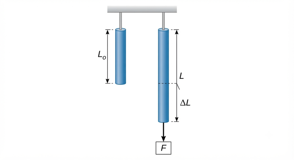
The strain is calculated using:
Where is the original length and is the change in length.
The strain gauge converts this mechanical deformation into an electrical measurement. The magnitude of the resistance change is related to the strain through the gauge factor.
Classification of Strain Gauges
Strain gauges can be classified according to their sensing material, physical arrangement, measurement direction, and electrical circuit configuration.
| Classification | Common types | Main purpose |
| Based on sensing material | Metallic foil, wire, semiconductor, thin-film | Detect mechanical deformation using different sensing technologies |
| Based on measurement direction | Linear gauge, double linear gauge, rosette | Measure strain along one or multiple directions |
| Based on grid arrangement | Tee, rectangular, delta rosette | Determine strain components when the strain direction is uncertain |
| Based on bridge configuration | Quarter-bridge, half-bridge, full-bridge | Convert resistance changes into an electrical output |
| Based on application | Load-cell, pressure-sensor, torque-sensor arrangements | Measure force, pressure, torque, or structural deformation |
These classifications describe different aspects of a strain gauge system. For example, a metallic foil gauge can be a linear gauge and can also be connected in a quarter-bridge circuit.
1. Linear Strain Gauges
A linear strain gauge measures strain primarily along one specified direction. Its sensing grid is aligned with the direction in which the strain is expected to occur.
Linear gauges are commonly used when the direction of loading is known, such as axial tension in a rod, compression in a structural member, or bending strain on a beam.
Working principle
When the specimen deforms along the gauge axis, the sensing grid experiences approximately the same longitudinal strain as the bonded surface. The corresponding resistance change is measured and converted into a strain value.
Linear gauges are available in different grid lengths, widths, resistance values, and configurations to suit different specimen sizes and strain distributions.
Some manufacturers use designations such as LY for particular linear gauge families. The exact dimensions and model characteristics depend on the manufacturer’s product range.
Applications
- Axial strain measurement in rods and bars.
- Bending tests on beams and structural members.
- Mechanical component testing.
- Experimental stress analysis.
- Strain measurement in industrial machinery.
2. Double Linear Strain Gauges
A double linear strain gauge incorporates two linear sensing grids in one assembly. The grids may be arranged parallel to each other or in another specified orientation, depending on the design.
When two grids are aligned in the same direction, they can provide measurements at closely spaced locations or support particular bridge arrangements. Other dual-grid designs may use different orientations for specialised measurements.
The actual measurement capability depends on the grid layout and the way the gauges are connected.
Applications
- Comparing strain at adjacent locations.
- Measuring strain in components with limited mounting space.
- Implementing selected bridge configurations.
- Investigating strain variations in mechanical structures.
3. Strain Gauge Rosettes
A strain gauge rosette consists of two or three sensing grids arranged at known angles on a common backing. It is used when the direction of the principal strain is unknown or when strain must be evaluated along multiple directions.
A single linear strain gauge measures strain only along its own axis. A rosette provides additional directional measurements that can be combined to determine the in-plane principal strains and their orientations under appropriate assumptions.
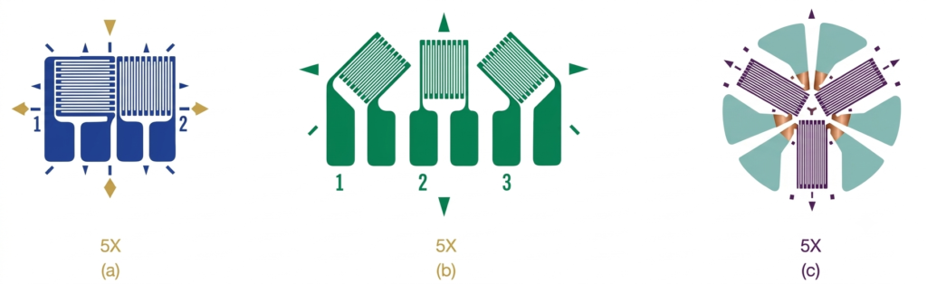
The common types of strain gauge rosettes are:
- Tee rosette.
- Rectangular rosette.
- Delta rosette.
- Membrane rosette and other application-specific multi-grid arrangements.
3.1 Tee Rosette Strain Gauge
A tee rosette is a two-element strain gauge arrangement with two grids oriented at 0° and 90° to each other.
The two grids measure normal strain in two perpendicular directions. These readings are useful when the relevant strain components are required along two known axes.
A tee rosette does not, by itself, provide the third independent directional measurement available from a three-element rosette. Additional information or assumptions may be needed to determine principal strain.
Applications: Biaxial strain measurement, mechanical testing, and selected structural investigations.
3.2 Rectangular Rosette Strain Gauge
A rectangular rosette is a three-element arrangement with sensing grids oriented at 0°, 45°, and 90°.
The three measured strains can be used to calculate the in-plane principal strains and the principal directions.
Let the measured strains be (\varepsilon_0), (\varepsilon_{45}), and (\varepsilon_{90}).
The normal strain components along the two perpendicular reference axes are:
The in-plane engineering shear strain is:
The principal strains are:
These equations assume the grids are correctly oriented and the measurements represent the same local strain field.
Applications: Stress analysis of machine components, structural testing, pressure-loaded parts, and materials research.
3.3 Delta Rosette Strain Gauge
A delta rosette is a three-element arrangement with grids oriented at 0°, 60°, and 120°.
The three directional measurements provide the information required to determine in-plane principal strains when the applicable strain-transformation relationships are used.
Delta rosettes are useful when a three-grid arrangement at equal angular intervals suits the available mounting area or the measurement requirements.
Applications: Experimental stress analysis, mechanical testing, and measurements on components with unknown principal strain directions.
3.4 Membrane Rosette and Special-Purpose Gauges
The term membrane rosette is used for particular multi-grid arrangements intended for specialised strain measurements. The precise grid layout and purpose vary by manufacturer and application.
Some specialised gauges are designed for use on thin membranes, pressure-sensitive structures, or components experiencing complex deformation.
Their suitability depends on the specimen geometry, strain field, operating environment, and calibration requirements.
4. Quarter-Bridge Strain Gauge Configuration
A quarter-bridge circuit uses one active strain gauge in a Wheatstone bridge. The remaining bridge arms are provided by fixed completion resistors or an appropriate completion network.
It is a relatively simple and economical arrangement for measuring strain.
Working principle
When the bridge is balanced, its differential output is ideally zero. Mechanical deformation changes the resistance of the active gauge, unbalancing the bridge and producing an output voltage.
For a small resistance change, the approximate output magnitude is:
Using the gauge factor (GF):
Where is the bridge excitation voltage.
These expressions assume a balanced bridge, one active arm, and a small strain-induced resistance change. Output polarity depends on the bridge wiring.
Quarter-bridge type I: Axial or bending strain
In this arrangement, one active gauge is mounted in the direction of the strain to be measured.
For axial strain, the gauge is aligned with the component’s longitudinal axis. For bending strain, the gauge is placed at a suitable location on the beam or structural member.
The resulting resistance change is measured using the bridge circuit.
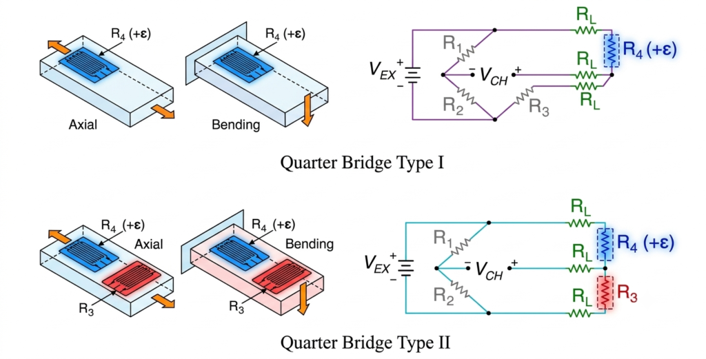
Quarter-bridge type II: Temperature compensation
Some quarter-bridge configurations incorporate a temperature-compensation arrangement, such as a dummy gauge, in addition to the active gauge.
The dummy gauge is placed where it experiences a similar temperature but negligible mechanical strain. The bridge is designed so that common temperature-induced resistance changes are reduced.
The precise resistor and gauge positions depend on the circuit design. A dummy gauge is not a substitute for correct installation, wiring, or temperature matching.
Advantages of a quarter-bridge circuit
- Simple construction.
- Low sensor cost.
- Requires only one active measuring grid.
- Suitable for many basic strain measurements.
Limitations
- Lower output sensitivity than some properly configured multi-active-gauge bridges.
- Temperature errors may be significant without compensation.
- Lead-wire resistance can influence accuracy.
- Stable excitation and signal amplification are usually required.
5. Half-Bridge Strain Gauge Configuration
A half-bridge circuit incorporates two active strain gauge elements in the Wheatstone bridge. The gauges can be arranged to increase sensitivity, compensate temperature effects, or distinguish between different strain components.
The actual performance depends on the placement and orientation of the gauges.
Half-bridge type I: Axial strain measurement
One gauge can measure the longitudinal strain, while the second is mounted in a perpendicular direction to measure transverse strain associated with Poisson’s effect.
For a suitable uniaxial elastic loading condition, the transverse strain is related to the longitudinal strain by:
Where:
- is transverse strain.
- is longitudinal strain.
- is Poisson’s ratio.
When the gauges are connected in an appropriate bridge arrangement, their resistance changes can be combined to improve sensitivity or compensate certain effects.
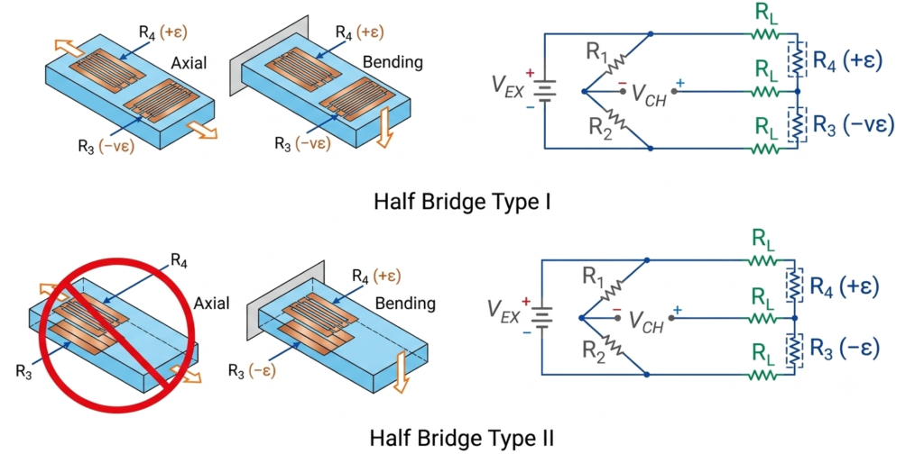
Half-bridge type II: Bending strain measurement
For a bending measurement, two gauges may be mounted on opposite sides of a beam. One experiences tensile strain while the other experiences compressive strain.
With the correct bridge connections, the strain responses reinforce one another. The arrangement can also reject common temperature effects when the gauges experience similar thermal conditions.
The circuit must be designed for the intended measurement; a half-bridge does not automatically reject every unwanted strain component.
Advantages of a half-bridge
- Can provide higher output sensitivity than a quarter-bridge.
- Can reduce temperature-related errors.
- Can be configured for axial or bending strain.
- May reduce the influence of unwanted common-mode effects.
6. Full-Bridge Strain Gauge Configuration
A full-bridge circuit uses four active strain gauge elements as the four arms of a Wheatstone bridge. It can provide a higher output signal and useful compensation when the gauges are arranged correctly.
Full-bridge configurations are common in load cells and other transducers where accurate measurement of force, weight, or mechanical loading is required.
Full-bridge type I: Bending strain measurement
Two gauges are arranged to experience tensile strain and two to experience compressive strain. Their bridge connections are selected so that the resistance changes reinforce the output caused by bending.
This arrangement can provide increased sensitivity to bending and reduce the effects of temperature changes common to the gauges.
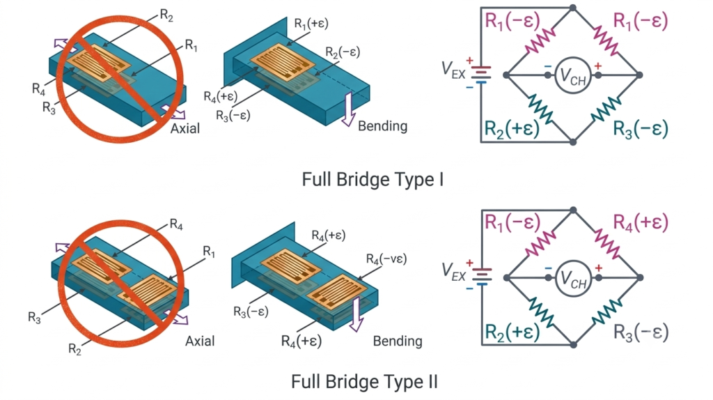
Full-bridge type II: Alternative bending arrangement
An alternative full-bridge layout uses gauge positions and orientations selected to distinguish the desired bending response from other strain components.
Depending on the arrangement, transverse strain caused by Poisson’s effect can contribute to the bridge output. The expected output should therefore be determined from the actual gauge orientations and bridge connections.
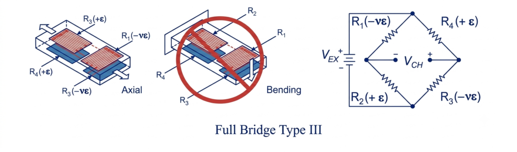
Full-bridge type III: Axial strain measurement
A full-bridge axial measurement arrangement can use two gauges aligned with the axial direction and two transverse gauges, positioned and connected to produce the required response.
The longitudinal gauges detect axial strain, while the transverse gauges detect the associated lateral strain. The bridge connections are selected to reinforce the intended axial response and compensate for common temperature effects.
This configuration can be useful when both sensitivity and temperature stability are important.
Advantages of a full-bridge circuit
- High sensitivity with a suitable gauge arrangement.
- Good potential for temperature compensation.
- Useful for load cells, force transducers, and weighing systems.
- Can be designed to reject unwanted strain components.
The full bridge requires four active gauge elements and careful installation. Its performance depends on the mechanical design, gauge matching, wiring, and calibration.
7. Metallic Foil Strain Gauges
Metallic foil strain gauges use a thin resistance-alloy grid bonded to an insulating backing. The grid is usually arranged in a folded pattern to provide a relatively long conductor within a small area.
These gauges are widely used in engineering laboratories and industrial measurement systems because they provide practical sensitivity and good measurement performance over their specified operating range.
Typical applications:
- Load cells and force transducers.
- Torque measurement.
- Structural strain analysis.
- Pressure transducers.
- Mechanical component testing.
8. Wire Strain Gauges
Wire strain gauges use a fine resistance wire arranged in a suitable grid pattern. Deformation changes the wire’s dimensions and therefore its electrical resistance.
Wire gauges are an established strain-measurement technology, although metallic foil gauges are common in many modern bonded applications.
Their performance depends on the wire material, construction, adhesive, installation method, and operating conditions.
9. Semiconductor Strain Gauges
Semiconductor strain gauges operate primarily through the piezoresistive effect. Mechanical stress changes the electrical resistivity of the semiconductor material, producing a resistance change that can be considerably larger than that of a conventional metallic gauge.
Their high sensitivity is useful in compact transducers and applications requiring small deformation measurements.
However, semiconductor gauges may have greater temperature sensitivity and different linearity characteristics than metallic foil gauges. Suitable compensation and calibration are important.
10. Thin-Film Strain Gauges
Thin-film strain gauges are manufactured by depositing a sensing material onto a suitable substrate or sensor structure.
This construction supports compact sensor designs and integration into specialised measurement devices.
Thin-film strain sensing is used in selected pressure sensors, industrial transducers, and applications where space, durability, or integration requirements influence sensor selection.
Characteristics of Strain Gauges
The important characteristics of strain gauges determine their suitability for a particular measurement task.
1. Sensitivity
Sensitivity describes the resistance response to applied strain. For a conventional resistance strain gauge, this is represented by the gauge factor.
A higher gauge factor generally produces a larger fractional resistance change for the same strain.
2. Accuracy and repeatability
Accuracy indicates how closely a measured value represents the actual strain. Repeatability describes how consistently the gauge system produces the same reading under repeated equivalent conditions.
Both depend on the gauge, bonding, instrumentation, calibration, and environment.
3. Measurement range
The allowable strain range depends on the sensing element, backing, adhesive, specimen, and manufacturer’s specifications. Exceeding the rated range can permanently damage the gauge or cause measurement errors.
4. Temperature stability
Temperature changes can affect gauge resistance, the specimen dimensions, and the bonding material. A suitable gauge and compensation method should be selected for the operating temperature range.
5. Gauge length and grid orientation
Gauge length determines the approximate region over which strain is averaged. Shorter gauges may be suitable for localised strain gradients, while longer gauges average strain over a larger area.
Grid orientation determines the direction of strain being measured.
6. Long-term stability
For long-term installations, the stability of the gauge, adhesive, protective coating, wiring, and measurement electronics is important. Moisture, corrosion, temperature cycling, and mechanical damage can affect long-term reliability.
7. Electrical compatibility
Gauge resistance, excitation voltage, bridge configuration, cable length, and amplifier input characteristics must be compatible with the measurement system.
Advantages of Strain Gauges
The main advantages of strain gauges include:
- High sensitivity to small mechanical deformations.
- Compact construction and low weight.
- Suitability for static and dynamic measurements when properly designed.
- Compatibility with electronic instrumentation and data acquisition systems.
- Availability of different configurations for axial, bending, and multidirectional strain.
- Use in both laboratory testing and industrial applications.
- Capability for long-term monitoring when suitable protection and installation methods are used.
Limitations of Strain Gauges
Strain gauge systems also have certain limitations:
- The electrical resistance change is often very small and requires suitable signal conditioning.
- Correct surface preparation and bonding are essential.
- Temperature variation can introduce apparent strain.
- Electrical noise and lead-wire resistance can affect measurements.
- Moisture, chemicals, and mechanical damage may reduce reliability.
- Calibration is necessary for accurate force, pressure, or torque measurement.
- A single linear gauge cannot determine the complete in-plane strain state when the principal directions are unknown.
Applications of Strain Gauges
Strain gauges are used in many engineering fields where deformation or mechanical loading must be measured.
Aerospace engineering
Strain gauges are installed on test structures and selected aircraft components to study deformation, loading, and structural behaviour during testing.
Bridges and civil structures
Structural monitoring systems use strain gauges to measure local deformation in bridges and other structures. The measurements help engineers evaluate load response and investigate structural performance.
Railway monitoring
Strain gauges can be used in railway testing and monitoring equipment to study loads, deformation, and mechanical behaviour in rails, bogies, and other components.
Torque and power measurement
Strain gauges mounted on a rotating shaft can measure torque. When shaft speed is also known, the transmitted mechanical power can be calculated.
Where is mechanical power, is torque, and is angular velocity in radians per second.
Vibration and dynamic testing
Strain gauges can measure time-varying deformation caused by vibration, impact, or cyclic loading. Appropriate instrumentation is required to capture the frequency and amplitude of the changing signal.
Bending and deflection analysis
Strain measurements on beams and structural members can help engineers determine bending behaviour. Deflection may be estimated when the geometry, boundary conditions, and mechanical model are known.
Tension and compression testing
Strain gauges measure deformation in materials and components subjected to tensile or compressive loading. They are used in laboratory tests, material evaluation, and equipment development.
Force and pressure measurement
When bonded to a suitably designed elastic element or diaphragm, strain gauges can be incorporated into load cells, force transducers, and pressure transducers.
How to Select the Right Type of Strain Gauge
The best strain gauge depends on the required measurement rather than the gauge type alone.
| Selection factor | What to consider |
| Strain direction | Use a linear gauge for a known direction or a rosette when multiple directions are required |
| Loading condition | Determine whether the component experiences axial loading, bending, torsion, or combined loading |
| Required sensitivity | Compare gauge factor, bridge configuration, and signal-conditioning requirements |
| Temperature | Check operating range, thermal expansion compatibility, and compensation methods |
| Available space | Select a suitable gauge length and grid geometry |
| Environmental conditions | Consider moisture, chemicals, vibration, and protective coatings |
| Measurement duration | Evaluate stability for short tests or long-term monitoring |
| Instrumentation | Ensure compatibility with the bridge, excitation supply, amplifier, and data acquisition system |
For most general-purpose bonded strain measurements, metallic foil gauges are a practical choice. Rosettes are more appropriate when the principal strain direction is unknown, while semiconductor gauges can be useful when very high sensitivity is needed and their temperature characteristics can be managed.
Conclusion
Different types of strain gauges are designed to measure deformation under different mechanical and environmental conditions. Linear gauges are suitable when the strain direction is known, while tee, rectangular, and delta rosettes provide measurements in multiple directions. Metallic foil, wire, semiconductor, and thin-film gauges offer different sensing characteristics.
Quarter-bridge, half-bridge, and full-bridge circuits provide alternative methods of converting resistance changes into measurable electrical signals. The appropriate choice depends on the required sensitivity, temperature stability, measurement range, loading condition, and instrumentation.
By selecting the correct gauge, installing it properly, and applying suitable compensation and calibration, engineers can obtain reliable strain measurements for structural testing, load cells, torque sensors, pressure transducers, and industrial monitoring systems.
Read Next:
- Transmitter: Types, Working Principle, and Examples
- SMART Transmitter: Working Principle, Components, Advantages
- Level Transmitter Calibration Procedure
- Level Transmitter: Types, Working Principle & Applications
- Differential Pressure Transmitter: Working Principle, Types
- Capacitance Differential Pressure Transmitter: Working Principle, Construction
- Piezoresistive Differential Pressure Transmitter: Working Principle, Diagram, Components, and Applications
- Strain-Gauge Differential Pressure Transmitter: Working Principle, Diagram, Components, and Applications
- Strain Gauge: Working Principle, Diagram, Types, and Applications
- Bonded and Unbonded Strain Gauges: Construction, Working Principle, and Differences