A Programmable Logic Controller (PLC) uses output modules to send control signals to external devices such as motors, contactors, solenoid valves, indicator lamps, and alarms. PLC output types are broadly classified into two main categories based on their switching technology: relay outputs and solid-state outputs. Solid-state outputs typically use transistors or TRIACs to switch electrical loads electronically without relying on mechanical contacts.
The selection of an output type depends on the connected load, switching frequency, operating voltage, response time, and application requirements.
Types of PLC Outputs
PLC output modules are classified according to the switching technology used to operate external devices. The main types include relay, transistor, TTL logic, and TRIAC outputs.
Relay outputs use mechanical contacts to switch electrical loads. Solid-state outputs use semiconductor components, such as transistors for DC applications and TRIACs for AC applications. TTL logic outputs are designed to provide digital signals for interfacing with electronic logic circuits.
Transistor outputs are available in different configurations, including open-collector, common-emitter, and emitter-follower types. They are generally used to operate indicator lamps, small DC relays, and other low-power DC devices. TRIAC outputs are suitable for switching low-power AC loads, such as lighting circuits, motor starters, and contactors.
PLC output modules may have a shared common terminal or electrically isolated channels. The selection of an appropriate output module depends on the connected devices, their voltage and current requirements, and the available power supply. In many applications, a separate power source is required to operate the external devices connected to the PLC.
Relay Outputs in PLC
Relay outputs are commonly used in PLC systems to operate electrical loads that require moderate switching current. They are suitable for applications involving currents of approximately 2 A, subject to the output module’s rated capacity. Another advantage is their low contact resistance, which makes them useful when minimal voltage drop across the switching contacts is required.
Relay contacts are generally classified into three configurations: Form A, Form B, and Form C. PLC output modules may incorporate any of these arrangements, although Form A and Form C are commonly used.
Types of Relay Contacts
Relay contacts are identified by their normal switching conditions and contact arrangements.
- Form A (Normally Open): This is a single-pole, normally open contact. The circuit remains open when the relay is de-energized and closes when the relay operates.
- Form B (Normally Closed): This is a single-pole, normally closed contact. The circuit remains closed in the normal condition and opens when the relay operates.
- Form C (Changeover Contact): This arrangement provides both normally open (NO) and normally closed (NC) connections through a common terminal. It is also known as a single-pole, double-throw (SPDT) contact.
A Form C contact offers the functionality of both Form A and Form B contacts. Its NO terminal can be used for normally open switching, while its NC terminal provides normally closed switching.

Common Relay Output Configuration
PLC relay output modules are available with common-connected contacts as well as electrically isolated contacts.
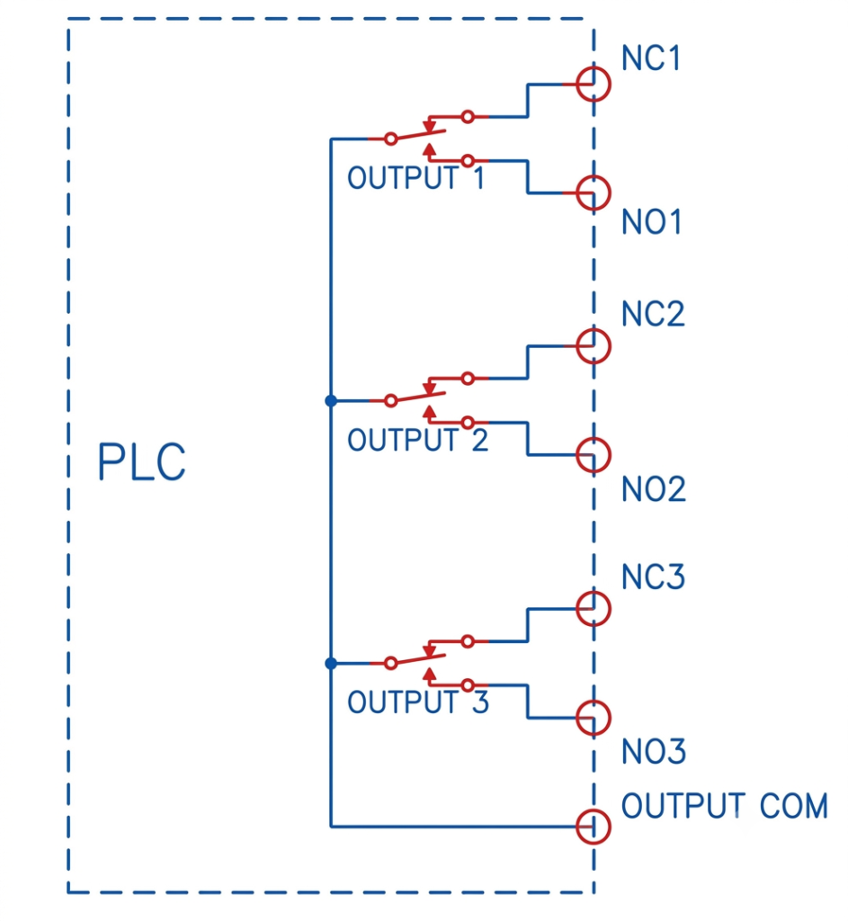
In a common-terminal arrangement, one side of multiple relay contacts is internally connected to a shared terminal, usually identified as OUTPUT COM. For example, a module containing three Form C relay contacts may have all three relay common connections linked to this terminal.
Because the contacts share a common connection, the associated output circuits must be wired with compatible common-reference arrangements. Different independent supply circuits cannot be treated as electrically isolated when they share this terminal.
Each relay output generally provides two switching connections:
- NO (Normally Open): The contact closes when the PLC output is energized.
- NC (Normally Closed): The contact remains closed when the PLC output is de-energized.
When an output is OFF, the common terminal is connected to its corresponding NC terminal. When the output is ON, the common terminal switches to the NO terminal.
Working of a PLC Relay Output with Common Contacts
Consider a PLC output module containing three Form C relay contacts connected to a common output terminal. The contacts can be used to control different electrical devices, such as indicator lamps, contactor coils, and solenoid valves.
For example, consider a circuit in which an AC supply is used to operate two indicator lamps.
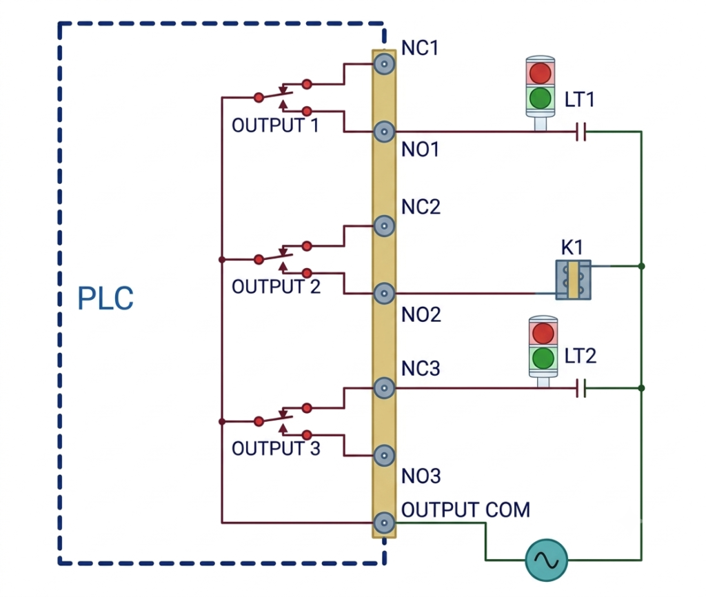
One lamp (LT1) is connected through the NO terminal of Output 1. It illuminates when Output 1 is energized because the relay closes the normally open contact.
Another lamp (LT2) is connected through the NC terminal of Output 3. It remains illuminated while Output 3 is OFF and switches off when the output is energized.
This arrangement can also provide a fault indication. If Output 3 is programmed to remain energized during normal operation, LT2 stays OFF while the PLC is running correctly. If the PLC loses power, the relay de-energizes and the NC contact returns to its closed position, illuminating LT2, provided the external supply remains available.
Such wiring can help maintenance personnel identify a PLC power failure or abnormal operating condition.
A relay output can also control an intermediate device, such as a contactor coil or solenoid. For example, Output 2 may operate a coil designated K1. The coil could belong to a motor starter or an actuator mechanism.
When the connected load requires more current than the PLC relay contact can safely handle, an appropriately rated interposing relay or contactor should be used. The coil voltage and AC/DC rating must match the available supply.
Isolated Relay Output Configuration
In an isolated relay output module, individual relay contacts have no common electrical connection between them. Each output provides an independent switching arrangement, allowing different power supplies and load circuits to be connected without sharing an internally connected common terminal.
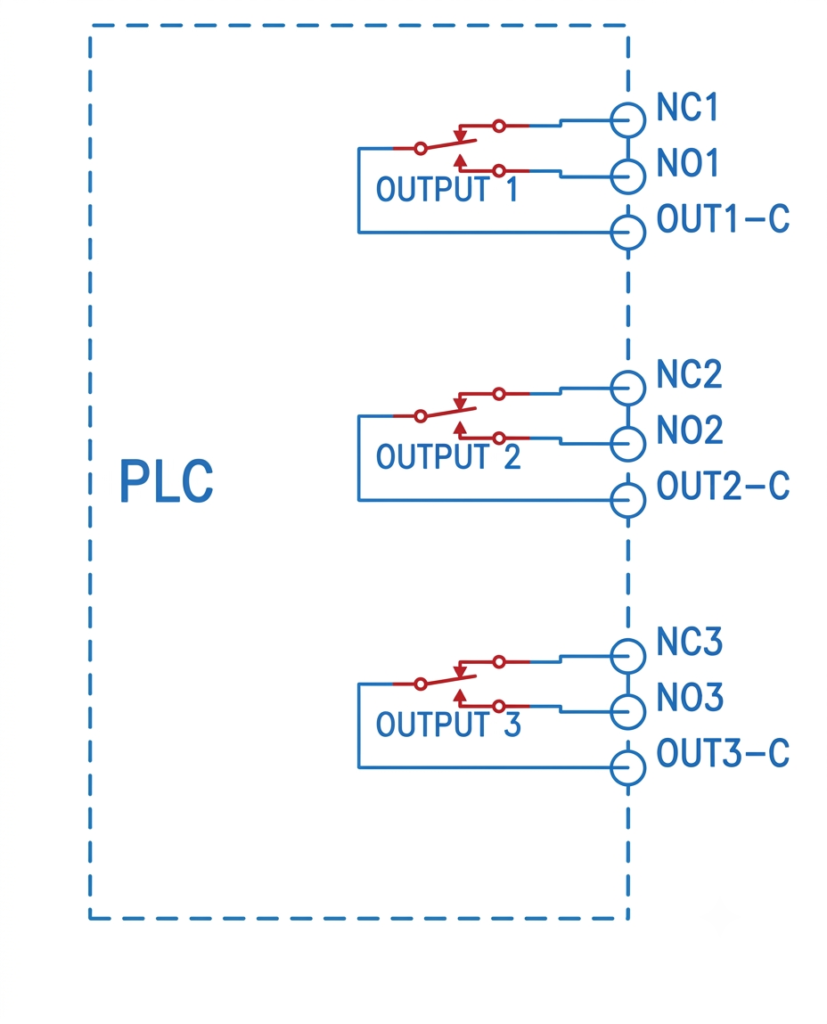
A typical isolated Form C output provides three terminals for each relay:
- C (Common): The movable contact connection.
- NO (Normally Open): Connects to the common terminal when the relay is energized.
- NC (Normally Closed): Connects to the common terminal when the relay is de-energized.
For a module containing three isolated Form C contacts, each output has its own separate C, NO, and NC terminals. This arrangement provides greater flexibility when controlling devices that operate at different voltages or use separate power supplies.
Applications of Isolated PLC Relay Outputs
Isolated relay outputs are useful when a PLC needs to control devices with different electrical supply requirements.
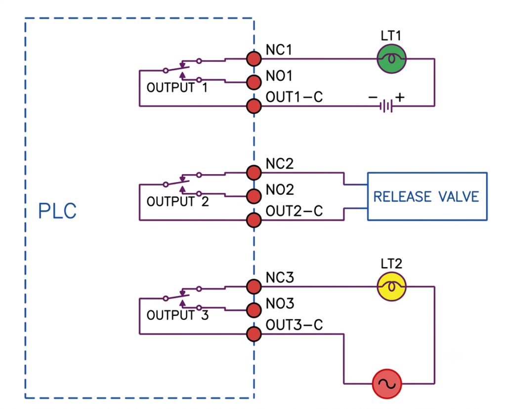
For example, consider a system with three independent outputs:
DC Indicator Lamp: Output 1 controls a DC lamp (LT1) using a separate DC power supply. If the lamp is connected through the NC contact, it remains ON when the PLC output is OFF. This arrangement can be used as a fault-status indicator.
AC Indicator Lamp: Output 3 controls another lamp (LT2) using an independent AC supply. Connecting it through the NC contact allows it to illuminate when Output 3 is de-energized.
Solenoid or Release Valve: Output 2 operates a release valve through its NC contact. Depending on the valve’s design, this arrangement can establish a particular release condition when the PLC output is de-energized.
Such configurations are useful in applications where equipment must move to a predetermined safe state following a control-system failure. However, the actual fail-safe condition must be verified against the actuator design and safety requirements.
Important Considerations for PLC Relay Output Wiring
When designing relay output circuits, consider the following points:
- Check the rated voltage and current of each relay contact before connecting a load.
- Use the NO or NC terminal according to the required operating condition.
- Verify whether the output module has common-connected or isolated contacts.
- Use separate power supplies where required by the load specifications and module arrangement.
- Use interposing relays or contactors for loads exceeding the PLC output contact rating.
- Provide suitable overcurrent protection for external output circuits.
Technical note: A PLC relay output does not necessarily provide a fail-safe function simply because an NC contact is used. The final condition depends on the external wiring, power availability, actuator design, and safety architecture.
Solid-State Outputs in PLC
Solid-state output modules use semiconductor devices instead of mechanical relay contacts to control external electrical loads. They offer faster switching, silent operation, and longer service life because they do not have moving contacts. The three commonly used types are transistor outputs, TRIAC outputs, and TTL logic outputs.
Transistor Output
Transistor output modules are primarily used for switching DC loads. They commonly use open-collector transistor configurations, in which the emitters or collectors of the output transistors are connected according to the module’s circuit arrangement.
Most PLC transistor output modules use optical isolation between the internal PLC circuitry and the output switching devices. This arrangement helps protect the controller from electrical disturbances originating in external circuits.
Transistor outputs are available in two configurations: NPN and PNP. These are commonly referred to as sinking and sourcing outputs, respectively.
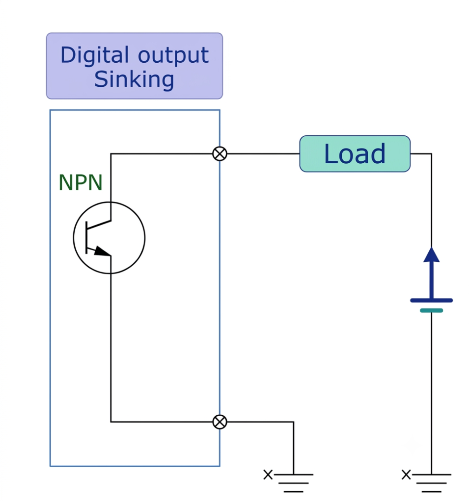
NPN (Sinking) Output
An NPN transistor output is called a sinking output because it provides a path for current to flow from the connected load towards the negative common terminal.
When the PLC output is activated, the transistor switches ON and allows current to flow through the connected device to the output common terminal (OUTCOM). The common terminal is generally connected to the negative side of the DC power supply.
PNP (Sourcing) Output
A PNP transistor output is known as a sourcing output because it supplies current from the positive power source to the connected load.
When the PLC output turns ON, the transistor conducts and provides a positive voltage at the output terminal. The load then receives current, which returns through the negative side of the power supply.
In this arrangement, the common terminal is generally connected to the positive side of the DC supply.
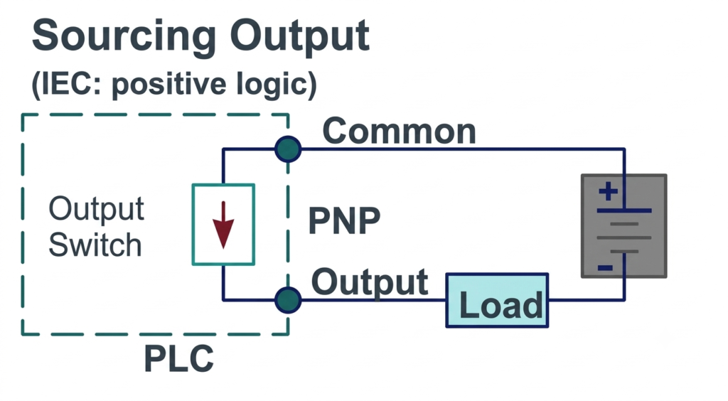
The main distinction between these configurations is the direction in which conventional current flows through the output circuit. An NPN output sinks current towards the negative supply, whereas a PNP output sources current from the positive supply.
Wiring of Transistor Output Modules
A transistor output module can operate different DC devices, including indicator lamps, relay coils, and solenoids.
For example, consider a PLC output module controlling three devices: an indicator lamp (LT1), a relay coil (K1), and another lamp (LT2).
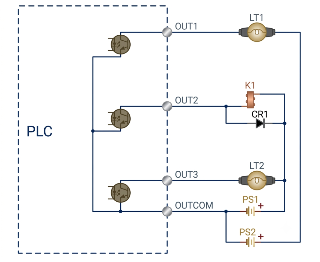
When Output 1 is activated, its transistor switches into conduction, completing the circuit and illuminating LT1. Similarly, when Output 2 turns ON, current flows through the relay coil K1, energizing it.
A protection diode is connected across an inductive load, such as a relay or solenoid coil. During normal operation, the diode remains reverse-biased. When the transistor switches OFF, the magnetic field in the coil collapses and produces a reverse voltage known as back EMF.
The diode provides an alternative path for the induced current, limiting the voltage spike and protecting the transistor from damage. This protection may be incorporated into the output module or provided externally, depending on the equipment design.
A transistor output module may also operate devices requiring different DC voltages. For example, one lamp may operate at 5 VDC, while a relay coil and another lamp use 24 VDC. The supply arrangement and common connections must follow the manufacturer’s wiring requirements. In a common-emitter sinking arrangement, the power supplies generally need a shared negative reference connected to OUTCOM.
TRIAC Output
TRIAC output modules are designed to switch AC electrical loads. Unlike transistor outputs, which are generally used for DC applications, TRIAC devices can control alternating current and are commonly found in PLC modules used for AC-powered equipment.
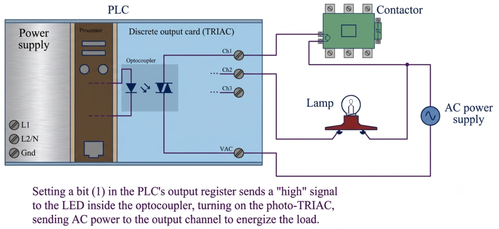
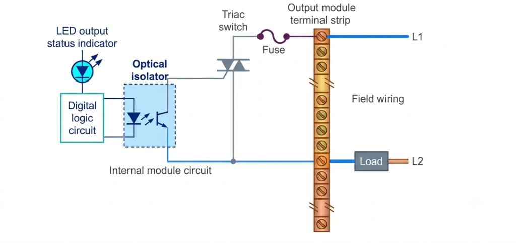
Each output uses a TRIAC as its switching element. When the corresponding PLC output is activated, the TRIAC receives a triggering signal and begins conducting current through the connected load.
Many TRIAC output modules use optical isolation to separate the PLC’s low-voltage electronic circuitry from the external AC switching circuit. This arrangement allows the PLC to control higher-voltage AC loads while providing electrical isolation between the control and output sections.
Some modules also incorporate zero-crossing switching circuits. These circuits trigger the TRIAC when the AC voltage approaches or crosses zero volts. This helps reduce electrical noise and switching disturbances that can occur when an AC load is energized at an arbitrary point in the voltage waveform.
Wiring of TRIAC Output Modules
A TRIAC output module generally uses a common terminal connected to one side of the AC supply. The individual output terminals are connected to the respective AC loads.
Many TRIAC output modules use optical isolation to separate the PLC’s low-voltage electronic circuitry from the external AC switching circuit. This arrangement allows the PLC to control higher-voltage AC loads while providing electrical isolation between the control and output sections.
Some modules also incorporate zero-crossing switching circuits. These circuits trigger the TRIAC when the AC voltage approaches or crosses zero volts. This helps reduce electrical noise and switching disturbances that can occur when an AC load is energized at an arbitrary point in the voltage waveform.
Wiring of TRIAC Output Modules
A TRIAC output module generally uses a common terminal connected to one side of the AC supply. The individual output terminals are connected to the respective AC loads.
When a PLC output is activated, the corresponding TRIAC conducts and allows current to flow through the connected device.
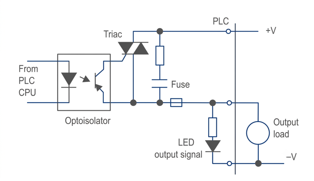
TRIAC output modules can operate AC-powered lamps, contactor coils, motor starters, and other compatible AC loads within their specified voltage and current ratings.
Unlike DC transistor output circuits, TRIAC circuits generally do not require a conventional flyback diode across an AC coil. A TRIAC normally stops conducting when the current falls below its holding-current level, typically around the AC current zero crossing.
However, highly inductive loads can produce voltage transients. In such cases, a series resistor-capacitor network, known as an RC snubber, may be connected across the load or switching device as recommended by the manufacturer.
The common terminal is connected according to the module’s specified AC wiring arrangement. It should not automatically be assumed that neutral is always the correct connection.
TTL Logic Output
TTL (Transistor-Transistor Logic) output modules provide digital signals for interfacing a PLC with external electronic circuits and logic devices. These outputs typically operate with 5 V DC logic levels.
TTL output modules generally provide a common terminal, identified as OUTCOM, which must be connected according to the required logic reference of the external circuit.
Many modules incorporate optical isolation to protect the PLC’s internal electronics from external electrical disturbances. However, some designs use direct electrical connections instead.
Certain TTL output modules also require an external 5 VDC supply to power their internal output circuitry.
An important consideration is the logic convention specified by the PLC manufacturer. TTL outputs may use positive logic or negative logic, which determines how the ON and OFF states are represented electrically and interpreted in the PLC program.
The ladder logic configuration must therefore be compatible with the output module’s specified logic arrangement.
Precautions When Using Solid-State PLC Outputs
Proper wiring and device selection are essential for reliable operation of solid-state output modules. The following points should be considered:
- Select the output module according to the voltage and current ratings of the connected devices.
- Use NPN or PNP transistor outputs according to the required sinking or sourcing arrangement.
- Provide suitable protection against inductive voltage spikes when switching DC relay and solenoid coils.
- Verify common-terminal connections and power supply polarity before energizing the circuit.
- Use suitable suppression devices for AC inductive loads where required.
- Check the logic-level requirements before connecting TTL outputs to external electronic circuits.
- Follow the manufacturer’s instructions for grounding, isolation, wiring, and load compatibility.
Conclusion
Solid-state PLC outputs provide fast and reliable switching for DC, AC, and digital logic applications. Transistor outputs are suitable for DC loads, TRIAC outputs are designed for AC loads, and TTL outputs are used for interfacing with electronic logic circuits. Selecting the correct output type and following the recommended wiring practices helps ensure safe and dependable PLC operation.
Read Next: