A transmitter is an important device used in industrial instrumentation, automation, and communication systems. In process industries, it measures parameters such as pressure, temperature, flow, and level and sends the measurement signals to a control system. Transmitters are widely used in cement plants, power stations, chemical industries, oil and gas facilities, and water treatment plants.
They help operators monitor process conditions, identify abnormal operating conditions, and maintain the required parameters. This article explains what a transmitter is, its working principle, different types, practical examples, applications, and selection criteria.
What Is a Transmitter?
A transmitter is a device that converts measured information into a signal suitable for transmission to another device or system. In industrial instrumentation, it receives an input from a sensing element, processes the measurement, and generates an analog or digital output.
For example, a pressure transmitter measures the pressure inside a pipeline and sends a corresponding signal to a programmable logic controller (PLC) or distributed control system (DCS). The control system can display the pressure, generate alarms, or use the measurement to regulate the process.
In communication systems, a transmitter performs a different function by generating signals that carry information through a communication channel, such as radio waves.
Working Principle of a Transmitter
An industrial transmitter operates by sensing a process variable, processing the resulting signal, and sending measurement information to a receiving device.
The operation generally involves the following steps:
- Sensing: A sensing element detects a physical parameter, such as pressure, temperature, or level.
- Signal conversion: The sensor converts the measured quantity into an electrical signal.
- Signal conditioning: The electronics amplify, filter, or linearize the signal as required.
- Signal processing: The instrument determines the measured value from the processed input.
- Output generation: An analog or digital signal is generated to represent the measurement.
- Signal transmission: The output is sent to a PLC, DCS, controller, indicator, or monitoring system.
The exact process depends on the sensing technology and transmitter design.
Example of a 4–20 mA Transmitter
Consider a pressure transmitter with a measuring range of 0–10 bar and an output range of 4–20 mA.
The output current is calculated using the following formula:
Where:
- = output current in mA
- = measured pressure in bar
- = lower range value
- = upper range value
If the measured pressure is 5 bar:
Therefore, a pressure of 5 bar produces an ideal output of 12 mA. This calculation assumes a linear measuring range and a correctly configured instrument.
Types of Transmitters
Transmitters can be classified according to the physical quantity measured, output signal, sensing principle, communication method, and intended application.
1. Types of Transmitters Based on the Measured Quantity
These instruments measure different process variables in industrial applications.
Pressure Transmitter
A pressure transmitter measures the pressure of liquids, gases, or steam in pipelines, compressors, vessels, and hydraulic systems. It converts the measured pressure into a standard output signal, commonly 4–20 mA, for monitoring and process regulation. Common types include gauge pressure, absolute pressure, and differential pressure transmitters.
In a piezoresistive pressure transmitter, the applied pressure causes a small deformation of a silicon sensing diaphragm. This changes the resistance of piezoresistive elements arranged in a Wheatstone bridge, producing a small electrical signal proportional to the applied pressure.
The transmitter amplifies and conditions this signal, compensates for temperature effects, and applies linearization where required. It then converts the processed measurement into a standard analog or digital output for a PLC, DCS, indicator, recorder, or controller.
Pressure transmitters are available in different measuring ranges, from low differential pressures to high process pressures, depending on their design.
Main Components
- Pressure-sensing element
- Signal-conditioning and amplifier circuit
- Output-conversion circuit
- Display unit, if provided
- Housing
- Process connection
Temperature Transmitter
A temperature transmitter converts the input from a resistance temperature detector (RTD) or thermocouple into a standard output signal, commonly 4–20 mA, for monitoring and process control. It is widely used in kilns, furnaces, boilers, motors, and process pipelines.
There are two common types:
1. RTD-Based Temperature Transmitter
An RTD transmitter measures temperature by detecting changes in the electrical resistance of a sensing element, commonly platinum. The transmitter processes the resistance signal, compensates for the sensor’s nonlinear response, and generates an output corresponding to the measured temperature.
2. Thermocouple-Based Temperature Transmitter
A thermocouple transmitter measures the thermoelectric voltage generated by two dissimilar metals. It applies cold-junction compensation, amplifies and linearizes the signal, and converts it into a standard output, typically 4–20 mA.
Some models also include sensor-break detection, reverse-polarity protection, and current-limiting circuits.
Advantages: Temperature transmitters provide standardized signals, improve noise immunity, simplify integration with control systems, and support reliable temperature monitoring in industrial processes.
Flow Transmitter
A flow transmitter measures the rate at which a liquid or gas flows through a pipe or channel and converts the measurement into a signal for monitoring and process control. Common measurement technologies include electromagnetic, vortex, ultrasonic, and differential-pressure flow measurement.
The working principle depends on the technology used. Electromagnetic flow meters measure flow based on the voltage induced when a conductive fluid moves through a magnetic field. Vortex flow meters determine flow by detecting vortices generated downstream of a bluff body, while differential-pressure flow meters calculate flow from the pressure difference created by a restriction in the pipe.
Ultrasonic flow meters use sound waves to determine fluid velocity. Transit-time models measure the difference in the travel times of ultrasonic signals moving with and against the flow, whereas Doppler models detect frequency shifts caused by particles or bubbles in the fluid.
The transmitter processes the sensor signals and provides an output, such as 4–20 mA or a digital communication signal, to a PLC, DCS, or other control system. Measurement accuracy depends on the flow technology, fluid properties, installation conditions, and instrument configuration.
Level Transmitter
A level transmitter measures the level of liquids, slurries, or bulk solids in tanks, silos, and process vessels and converts the measurement into a signal for monitoring and control. Common measurement technologies include radar, ultrasonic, hydrostatic pressure, and differential pressure.
The working principle depends on the technology used. Radar transmitters determine the level by measuring the travel time or frequency shift of electromagnetic waves reflected from the material surface. Ultrasonic transmitters use the travel time of sound waves, while hydrostatic transmitters calculate liquid level from the pressure exerted by the liquid column.
Differential-pressure transmitters determine liquid level by measuring the pressure difference between two points, accounting for vessel pressure and installation conditions where necessary. The transmitter processes the measurement and sends an output, commonly 4–20 mA or a digital signal, to a PLC, DCS, or other monitoring system. Measurement accuracy depends on the sensing technology, material properties, vessel conditions, and instrument installation.
Humidity Transmitter
A humidity transmitter measures the moisture content of air or other gases and converts the measurement into a signal for monitoring and control. It commonly measures relative humidity and may also calculate parameters such as dew point, depending on its design.
The working principle depends on the sensing technology. Capacitive humidity sensors detect changes in capacitance caused by moisture absorption, while resistive sensors measure changes in electrical resistance as humidity varies. The transmitter processes the sensor signal and provides an output, such as 4–20 mA or a digital communication signal, to a control or monitoring system.
Humidity transmitters are widely used in HVAC systems, warehouses, drying processes, pharmaceutical facilities, and environmental monitoring to maintain the required moisture conditions.
pH Transmitter
A pH transmitter measures the acidity or alkalinity of a liquid by processing the electrical signal from a pH sensor. It converts the sensor input into a standard output, such as 4–20 mA or a digital signal, for monitoring and process control.
The working principle is based on the voltage generated by a pH-sensitive electrode in response to the hydrogen ion activity of the solution. The transmitter processes this voltage, applies temperature compensation where supported, and converts it into a pH value.
pH transmitters are widely used in water treatment plants, chemical industries, pharmaceutical manufacturing, and process laboratories to monitor liquid quality and maintain the required chemical conditions.
2. Types Based on Output Signal and Communication
These categories describe how measurement information is delivered to the receiving system.
Analog Transmitter
An analog transmitter converts a measured physical quantity, such as pressure, temperature, flow, or level, into a continuous electrical signal proportional to the measurement. Common industrial output signals include 4–20 mA current and 0–10 V voltage.
The 4–20 mA current loop is widely used in process instrumentation because it provides reliable signal transmission over long cables and offers better resistance to electrical noise than many low-level voltage signals. The 4 mA lower-range value, known as a live zero, also helps distinguish a valid zero measurement from certain wiring faults, such as a broken loop that causes the current to fall close to 0 mA.
Digital Transmitter
Digital transmitters process and communicate measurement data in digital form using protocols such as Modbus and PROFIBUS. Depending on the device, they can transmit process values, configuration settings, and diagnostic information to a control system.
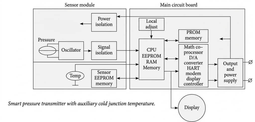
In smart and fieldbus instruments, the sensor output may be converted into digital form close to the sensing element, reducing susceptibility to certain types of electrical noise and signal degradation. Some sensing techniques represent the measured quantity through frequency, pulse duration, or phase shift rather than signal amplitude.
For example, a capacitive pressure sensor can be incorporated into an oscillator circuit in which changes in capacitance produce corresponding changes in frequency. Similarly, an ultrasonic flow meter can determine fluid flow by measuring the transit time of ultrasonic waves through the fluid.
A microprocessor can measure frequency and time intervals using a precise clock. When a sensor provides a directly usable digital or time-based output, an analog-to-digital converter (ADC) may not be required at that measurement stage. This can eliminate ADC quantization errors, although overall accuracy still depends on sensor characteristics, clock precision, and other sources of measurement error.
Smart Transmitter
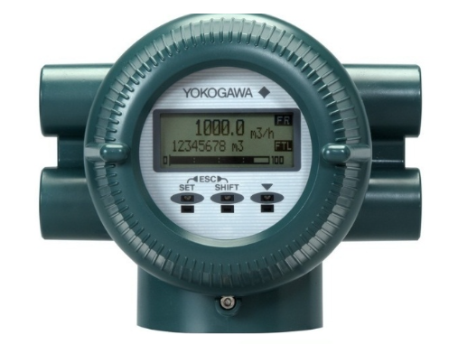
A smart transmitter uses a microprocessor and digital electronics to process measurements and provide advanced functions, such as remote configuration, calibration support, and diagnostics. Many models combine a 4–20 mA output with HART communication, allowing the instrument to send the primary process measurement while exchanging additional digital information.
This digital information may include instrument tag names, calibration parameters, configuration settings, and sensor diagnostic data. Some smart transmitters also report their health status according to NAMUR NE 107, which classifies diagnostic conditions as Failure, Function Check, Out of Specification, or Maintenance Required.
These features help technicians configure instruments remotely, assess measurement performance, identify potential faults, and plan maintenance without always needing physical access to the device.
HART Transmitter
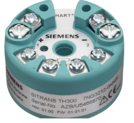
Digital communication protocols such as HART and FOUNDATION Fieldbus enable remote monitoring, device configuration, diagnostics, and calibration of transmitters. In FOUNDATION Fieldbus systems, digital communication can also support closed-loop process control.
Digital signals represent information using binary states, typically 0 and 1. This makes digital communication relatively resistant to noise, provided interference does not cause the receiver to misinterpret one state as the other. Error-detection mechanisms can identify certain transmission errors, although they cannot eliminate every possible error.
HART communication operates at 1,200 bit/s, making it suitable for transmitting measurement data and accessing device information, but generally less suitable for fast control loops when used alone. Consequently, many HART installations use the analog 4–20 mA signal for the primary control measurement while the digital signal provides configuration and diagnostic information.
HART transmitters are commonly connected in point-to-point configurations. A multidrop arrangement can connect multiple devices to the same pair of wires, but it has limitations and is less common in applications requiring individual analog control signals.
HART transmitters can be configured and calibrated using a compatible HART communicator, which allows technicians to access device parameters, perform configuration tasks, and carry out supported calibration procedures.
Fieldbus Transmitters
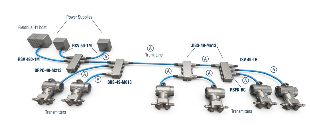
FOUNDATION Fieldbus transmitters use the H1 communication protocol, which operates at 31.25 kbit/s and supports digital communication and closed-loop control. Multiple devices, often around 12 to 16 depending on network design and operating requirements, can share the same pair of wires in a multidrop configuration. These devices may come from different manufacturers, provided they meet the applicable compatibility requirements.
Unlike a conventional 4–20 mA instrument loop, FOUNDATION Fieldbus can carry measurement values, device status, diagnostic information, and control data over the same digital network. Supported function blocks within field devices can perform control, calculation, and logic functions. This can reduce reliance on a centralized controller for certain basic control tasks, although the overall system architecture still determines the role of the DCS.
Fieldbus transmitters also communicate measurement-quality information, such as Good, Bad, or Uncertain, along with process readings. Control functions can use this status to reject unreliable measurements, select an alternative input, calculate an average from valid readings, or initiate an appropriate response.
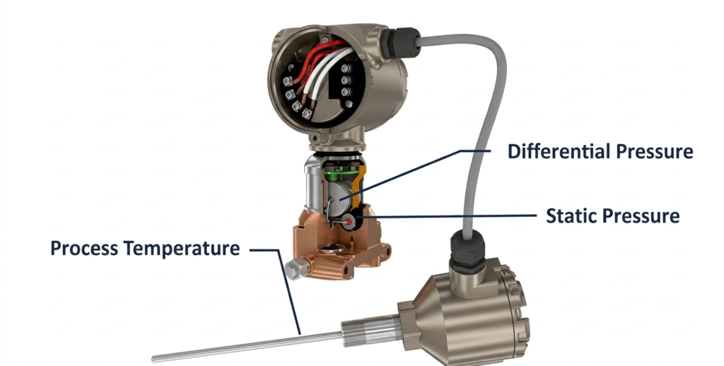
Some smart transmitters also use auxiliary sensors to compensate for the effects of temperature or static pressure on the primary measurement. For example, a multivariable flow transmitter may measure differential pressure, static pressure, and temperature to calculate a compensated flow rate. Although several variables are measured, the instrument may provide one primary calculated output, with additional variables available through digital communication.
Wireless Transmitter
A wireless transmitter sends measurement information through a wireless communication link rather than relying entirely on wired signal connections. Depending on the application, it may use WirelessHART, Wi-Fi, Bluetooth, or LoRaWAN.
Wireless instruments are particularly useful at remote measurement points or where installing signal cables would be difficult or expensive.
3. Types Based on Sensing Principle
The sensing principle determines how the instrument detects a physical change.
Capacitive Transmitter
A capacitance-level transmitter measures the level of liquids or powdery solids by detecting changes in capacitance caused by variations in the material level. It can be used for continuous, long-distance level monitoring in industrial tanks, vessels, and storage systems. Depending on the sensor design and the electrical properties of the material, it can measure both conductive and non-conductive media.
The working principle is based on the change in capacitance between sensing electrodes as the material level changes. In a differential-pressure-based capacitive transmitter, pressure from the process acts on a sensing diaphragm through the high- and low-pressure chambers. The resulting diaphragm displacement changes the capacitance, which is converted into an electrical signal proportional to the applied differential pressure.
The transmitter’s electronic circuit processes and digitizes the sensor signal, applies compensation and linearization where required, and generates an output corresponding to the measured level. Depending on the model, it can provide a 4–20 mA signal along with digital communication, configuration, and diagnostic functions.
Capacitance-level transmitters are widely used in chemical processing, water treatment, and bulk-material storage. Their measurement performance depends on the material’s dielectric properties, sensor configuration, vessel conditions, and correct calibration.
Piezoelectric Transmitter
A piezoelectric transmitter uses materials that generate an electrical charge when subjected to mechanical stress. The sensing element converts changes in pressure, force, or vibration into an electrical signal, which is then processed to represent the measured quantity.
These transmitters are particularly suitable for dynamic measurements, such as rapidly changing pressure, vibration, and impact force, because they respond quickly to mechanical changes. Depending on the design, the processed signal can be sent to monitoring equipment or a control system for analysis.
Inductive Transmitter
An inductive transmitter detects changes in inductance or electromagnetic coupling to measure parameters such as position, displacement, or movement. The sensing element responds to changes in the position of a magnetic core, coil, or metallic target and produces an electrical signal corresponding to the measured quantity.
The transmitter processes this signal and converts it into a standard output, such as 4–20 mA or a digital signal, for monitoring and control. Inductive sensing is commonly used in displacement measurement, position feedback, industrial automation, and machinery monitoring.
Ultrasonic Transmitter
An ultrasonic transmitter measures the level of liquids or bulk materials in tanks, vessels, silos, and open channels using high-frequency sound waves. It sends ultrasonic pulses toward the material surface and measures the time taken for the reflected echoes to return. Based on this travel time, the transmitter calculates the distance to the surface and determines the material level using the configured installation height.
The measured value is processed and transmitted to a PLC, DCS, or other monitoring system through a standard output, such as a 4–20 mA signal or digital communication. Ultrasonic transmitters are widely used in water and wastewater treatment plants, mining, power generation, and industrial storage systems. Since they generally operate without direct contact with the measured material, they reduce problems associated with corrosion, sticking, and mechanical wear. However, foam, vapour, temperature variations, and irregular material surfaces can affect measurement accuracy.
Thermal Transmitter
A thermal transmitter uses heat transfer or temperature-dependent changes to measure a physical parameter, such as gas flow or temperature. Its sensing element detects changes in heat transfer or temperature, and the electronic circuit processes the measurement and generates an output signal for monitoring and control.
For example, a thermal mass flow transmitter measures gas flow by detecting how flowing gas carries heat away from a heated sensor. The measured heat loss is used to determine the gas mass flow rate.
Thermal sensing is used in gas flow measurement, temperature monitoring, and industrial process control. These descriptions represent different sensing principles or instrument designs; they are not mutually exclusive categories of complete transmitters.
4. Special-Purpose Industrial Transmitters
Some instruments are designed for specific measurement requirements or operating environments.
Differential Pressure Transmitter
A differential pressure transmitter measures the pressure difference between two points in a process system and converts it into an electrical signal for monitoring and control. It is commonly used to measure flow across an orifice plate, monitor filter blockage, determine liquid level in pressurized tanks, and measure pressure drop across equipment.
The transmitter senses pressure at its high- and low-pressure ports. The pressure difference causes a change in the sensing element, which the electronic circuit processes and converts into a standard output, typically 4–20 mA, or a digital signal.
For example, when installed across an orifice plate, the transmitter measures the pressure difference created by flowing fluid. The control system uses this differential pressure to calculate the flow rate. In filter monitoring, an increasing pressure difference can indicate that the filter is becoming clogged and requires cleaning or replacement.
Multivariable Transmitter
A multivariable transmitter measures or calculates multiple process variables and combines them to determine parameters such as density, concentration, or mass flow rate. Depending on the model, it may measure differential pressure, static pressure, and process temperature for compensated flow measurement.
For example, a transmitter installed across an orifice plate measures the differential pressure, static line pressure, and process temperature to calculate standard volumetric flow or mass flow. These measurements allow compensation for changes in operating conditions, improving the accuracy of the calculated flow rate.
Similarly, pressure and temperature measurements can be used to determine fluid density when the appropriate fluid properties and calculation methods are available. Auxiliary sensors or compensation algorithms may also help reduce temperature-related measurement errors. Depending on its design, the instrument can provide a 4–20 mA output along with additional digital measurement and diagnostic data.
Explosion-Protected Transmitter
An explosion-protected transmitter is designed and certified for use in hazardous areas where flammable gases, vapours, or combustible dust may be present. Its enclosure and electrical design use a specified protection method to reduce the risk of ignition under defined operating conditions.
Depending on the design, protection may be provided through flameproof enclosures, intrinsic safety, or other approved methods. The transmitter converts the measured process variable, such as pressure, temperature, flow, or level, into a standard output signal for monitoring and control.
These transmitters are commonly used in oil and gas facilities, refineries, chemical plants, and other industries with potentially explosive atmospheres. The protection type, equipment certification, gas or dust group, and temperature class must match the hazardous-area classification and installation requirements.
Sanitary Transmitter
A sanitary transmitter is designed for hygienic process environments where cleanliness and contamination control are essential. It features smooth, easy-to-clean surfaces and hygienic process connections that help prevent material buildup and reduce the risk of microbial contamination.
Depending on the application, sanitary transmitters can measure pressure, temperature, flow, or liquid level. They are commonly manufactured from corrosion-resistant materials, such as stainless steel, and may support clean-in-place (CIP) or sterilize-in-place (SIP) procedures.
These transmitters are widely used in food and beverage processing, dairy production, pharmaceutical manufacturing, and biotechnology facilities. The materials, surface finish, seals, and process connections must meet the applicable hygiene and industry requirements.
5. Types of Transmitters Used in Communication Systems
In radio communication, a transmitter generates signals that carry information through electromagnetic waves.
AM Transmitter
An amplitude modulation (AM) transmitter transmits information by varying the amplitude of a high-frequency carrier signal according to the instantaneous value of the message signal, while the carrier frequency remains essentially constant.
The transmitter combines the message signal, such as audio, with the carrier wave through a modulation circuit. The modulated signal is then amplified and fed to an antenna for radiation as electromagnetic waves.
AM transmitters are commonly used in medium-wave and shortwave radio broadcasting. Their relatively simple receiver design makes AM suitable for wide-area broadcasting, although the signals can be more susceptible to noise and interference than frequency-modulated signals.
FM Transmitter
A frequency modulation (FM) transmitter transmits information by varying the instantaneous frequency of a carrier signal according to the message signal, while maintaining a nearly constant carrier amplitude.
The transmitter combines the information signal, such as audio, with the carrier using a frequency modulator. The resulting FM signal is then amplified and supplied to an antenna for transmission as electromagnetic waves.
FM transmitters are widely used in FM radio broadcasting, wireless communication, and two-way radio systems. Compared with AM, FM generally offers better resistance to amplitude noise and interference, resulting in clearer audio under suitable reception conditions.
SSB Transmitter
A single-sideband (SSB) transmitter transmits only one sideband, either the upper sideband (USB) or the lower sideband (LSB), of an amplitude-modulated signal. The carrier and the other sideband are suppressed or significantly reduced, depending on the implementation.
The transmitter generates the modulated signal by combining the information signal with a carrier and filtering out the unwanted sideband. This reduces the required transmission bandwidth and can improve power efficiency compared with conventional double-sideband AM.
SSB transmitters are commonly used in shortwave radio, amateur radio, marine communication, and other two-way radio systems where efficient use of bandwidth and transmission power is important.
Direct-Conversion Transmitter
A direct-conversion transmitter converts a baseband information signal directly to the required radio frequency (RF) without using a separate intermediate-frequency (IF) stage. It typically uses a mixer to combine the baseband signal with a local oscillator signal, generating the desired RF output.
The resulting signal passes through filtering and amplification stages before being supplied to the antenna for transmission. By eliminating the intermediate-frequency stage, this architecture can reduce circuit complexity, component count, and equipment size.
Direct-conversion transmitters are used in wireless communication systems, including cellular devices, Wi-Fi equipment, and software-defined radio platforms. Their performance depends on factors such as oscillator stability, unwanted signal components, and the accuracy of the frequency-conversion circuitry.
Superheterodyne-Based Transmitter
A superheterodyne-based architecture uses frequency-conversion stages, including an intermediate frequency in relevant designs, to generate the desired transmission signal.
These systems are used in radio broadcasting, telecommunications, and wireless communication. Their design differs from industrial measurement transmitters because their primary purpose is to transmit information rather than measure a process variable.
Examples of a Transmitter
The following examples show how different designs operate in practical situations.
| Example | Working and application |
| Pressure transmitter | Measures compressed-air pressure and sends the measurement to a PLC or DCS. |
| Temperature transmitter | Converts an RTD or thermocouple signal into a standard output for process monitoring. |
| Flow transmitter | Measures water or process-fluid flow for consumption monitoring or automatic flow regulation. |
| Level transmitter | Measures the level of cement in a silo to help operators monitor material inventory. |
| Wireless pressure transmitter | Sends pressure readings from a remote pumping station to a monitoring system. |
| FM radio transmitter | Generates a frequency-modulated signal carrying audio information. |
For example, a pressure transmitter installed on a cement plant’s compressed-air pipeline can provide continuous pressure readings to the control room. Operators can use these readings to identify pressure drops and investigate potential leaks or compressor problems.
Applications of Transmitters
Transmitters are used in industries where process measurements or communication signals must be monitored, transmitted, or processed.
| Industry | Typical applications |
| Cement plants | Kiln pressure, process temperature, silo level, and material flow measurement |
| Power plants | Boiler pressure, steam temperature, water level, and flow monitoring |
| Oil and gas | Pipeline pressure, flow, tank level, and temperature measurement |
| Chemical industries | Pressure, temperature, pH, and flow monitoring |
| Water treatment | Water flow, tank level, pressure, and pH measurement |
| HVAC systems | Air pressure, humidity, temperature, and airflow monitoring |
| Food and pharmaceutical industries | Hygienic pressure, temperature, and level measurement |
| Telecommunications | Radio, television, and wireless signal transmission |
Advantages of Transmitters
The main advantages of using industrial transmitters include:
- Remote monitoring: Operators can observe process measurements in a control room without visiting each measurement point.
- Improved automation: Measurement signals provide feedback to controllers and automated equipment.
- Standardized interfaces: Common analog and digital signals simplify integration with PLCs, DCSs, indicators, and controllers.
- Operational safety: Remote measurements help operators identify abnormal process conditions.
- Diagnostic capabilities: Smart instruments can report certain sensor faults and provide configuration information.
- Reduced manual readings: Continuous measurements reduce dependence on frequent manual checks.
- Flexible installation: Wired and wireless options support different site conditions and measurement requirements.
The actual benefits depend on the instrument’s design, installation, calibration, configuration, and maintenance.
Difference Between a Transmitter and a Transducer
A transducer converts one form of energy or physical quantity into another. A transmitter processes measurement information and provides an output signal suitable for transmission.
| Feature | Transmitter | Transducer |
| Main function | Provides a signal representing a measurement or information | Converts energy or a physical quantity into another form |
| Output | Commonly a standardized analog or digital signal | May be electrical, mechanical, optical, or another form |
| Signal conditioning | Often includes signal-processing and output circuitry | May or may not include signal conditioning |
| Example | 4–20 mA pressure transmitter | Thermocouple sensing element |
| Application | Process monitoring and control | Sensing and energy conversion |
A transmitter may contain a transducer, and some instruments combine sensing, signal conditioning, and transmission functions in one assembly.
Difference Between a Transmitter and a Receiver
A transmitter sends information, whereas a receiver accepts an incoming signal and extracts the information it carries.
| Feature | Transmitter | Receiver |
| Main function | Sends information | Receives information |
| Signal processing | Prepares the signal for transmission | Processes the incoming signal |
| Example | FM broadcasting station | FM radio |
| Direction of information | Toward the receiving system | From the transmitting system |
In industrial instrumentation, the receiving device may be a PLC input module, DCS, controller, or indicator. In radio communication, it may be a radio receiver or another compatible wireless device.
How to Select a Transmitter
Selecting the right instrument requires consideration of the process conditions, measurement requirements, and receiving system.
- Measured parameter: Identify whether the application requires pressure, temperature, flow, level, humidity, pH, or another measurement.
- Measurement range: Choose a range that covers normal operating conditions and expected process variations.
- Accuracy: Match the required accuracy to the process and control objectives.
- Output signal: Confirm compatibility with the receiving equipment, including the required analog signal or digital protocol.
- Process connection: Verify the connection type, pressure rating, and material compatibility.
- Environmental conditions: Consider dust, moisture, vibration, ambient temperature, and corrosive exposure.
- Hazardous-area requirements: Confirm the required protection method and certification for hazardous installations.
- Maintenance and diagnostics: Evaluate calibration requirements, accessibility, and diagnostic functions.
- Installation conditions: Check power supply, grounding, cable routing, communication distance, and potential electromagnetic interference.
- Total cost: Consider purchase price, installation, maintenance, calibration, and expected service life.
For critical applications, selection should comply with the applicable engineering standards, process specifications, and safety requirements.
Conclusion
A transmitter converts measured information into a signal that can be sent to another device or system. In industrial instrumentation, it supports the monitoring and control of pressure, temperature, flow, level, and other process variables. Common types include pressure, temperature, flow, level, analog, digital, smart, and wireless transmitters.
Understanding their working principles, output signals, and applications helps engineers choose suitable instruments for reliable process monitoring and automation.
Read Next: