Thermowell insertion and immersion length are two critical dimensions that determine the accuracy, response time, and reliability of temperature measurement in industrial processes. Selecting the correct insertion and immersion lengths ensures the temperature sensor measures the actual process temperature while remaining protected from harsh operating conditions.
Temperature is one of the most important process variables in industrial applications, directly affecting product quality, process efficiency, and equipment safety. RTDs and thermocouples are commonly used to measure process temperature, but they are often exposed to harsh conditions such as high pressure, high temperature, corrosive chemicals, and high flow velocities that can damage the sensing element.
To protect these sensors, industries use a thermowell – a hollow metal tube that isolates the temperature sensor from the process while allowing it to sense the process temperature accurately. However, simply installing a thermowell is not enough. Selecting the correct insertion and immersion lengths is equally important for proper sensor installation and optimal measurement performance.
This article explains the fundamentals of thermowell insertion and immersion lengths, including their definitions, differences, selection guidelines, calculations, applications, and relevant industry standards.
Summary Table: Thermowell Insertion and Immersion Length
| Feature | Insertion Length | Immersion Length |
|---|---|---|
| Definition | The length of the thermowell that extends inside the process from the mounting point to the tip. | The effective length of the temperature sensor (RTD, thermocouple, etc.) exposed to the process temperature. |
| Associated Component | Thermowell | Temperature sensor (RTD, thermocouple, etc.) |
| Purpose | Determines how deeply the thermowell projects into the process while protecting the sensor. | Ensures the sensing element is sufficiently immersed for accurate temperature measurement. |
| Depends On | Thermowell design, process connection, and installation method. | Sensor length, sensing element location, and whether the sensor tip reaches the thermowell bottom. |
| Measurement Reference | Measured from the process connection (mounting face) to the thermowell tip. | Measured from the process connection to the sensor’s sensing tip. |
| Function | Protects the sensor from pressure, corrosion, abrasion, and flow. | Directly measures the process temperature. |
| Typical Relationship | Usually equal to or slightly greater than the sensor immersion length. | Usually equal to or very close to the insertion length when using a spring-loaded sensor. |
| Can They Differ? | Yes. A longer thermowell can accommodate different sensor lengths. | Yes. A shorter sensor may not reach the thermowell tip, reducing measurement accuracy. |
| Primary Design Consideration | Mechanical strength, vibration resistance, pressure rating, and response time. | Measurement accuracy, response time, and proper positioning of the sensing element. |
| Example | A thermowell with a 150 mm insertion length extends 150 mm into the process. | An RTD with a 150 mm immersion length has its sensing tip positioned at the bottom of the thermowell. |
What is a Thermowell and Why is it Used?
In industrial processes, temperature is commonly measured using sensors such as RTDs and thermocouples. While these sensors can be inserted directly into the process fluid, many applications involve high temperatures, high pressures, corrosive chemicals, abrasive media, or high flow velocities that can damage the sensing element.
Additionally, replacing a failed sensor would require opening the process, which can lead to downtime, safety risks, and increased maintenance costs.
To overcome these challenges, a thermowell is used. A thermowell is a hollow, closed-end metal tube that is permanently installed in a pipe, tank, or vessel. The temperature sensor is inserted inside the thermowell instead of directly into the process fluid. The thermowell transfers the process temperature to the sensor while protecting it from harsh operating conditions.
Since only the thermowell comes into contact with the process, the sensor can be removed or replaced without draining the system or interrupting the process, making maintenance faster, safer, and more economical.
This protective arrangement also improves the reliability and service life of temperature sensors, making thermowells a standard choice in industries such as oil & gas, chemical processing, power generation, pharmaceuticals, food & beverage, and water treatment.
Components of a Thermowell Assembly:
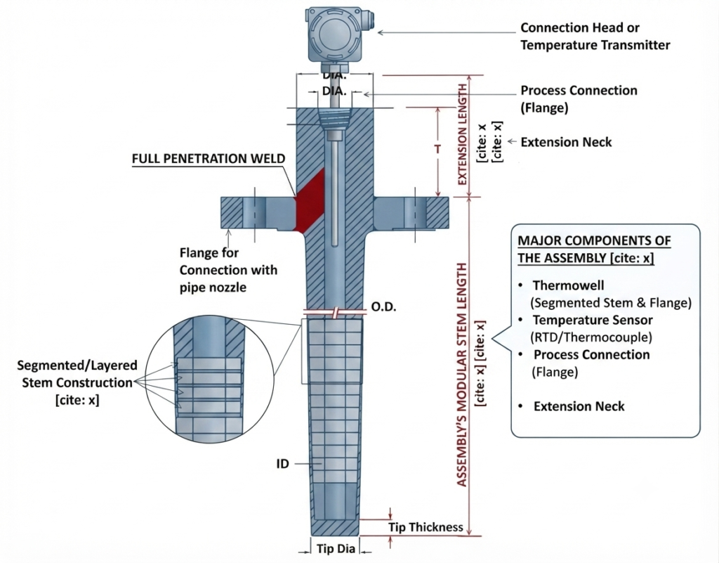
A complete thermowell assembly consists of several components that work together to provide accurate and reliable temperature measurement while protecting the sensing element from the process. Although the exact construction may vary depending on the application, a typical assembly includes the following components:
- Thermowell: The thermowell is a hollow, closed-end metal tube that is permanently installed in the pipe, vessel, or tank. It acts as a protective barrier between the process fluid and the temperature sensor while efficiently transferring heat from the process to the sensor.
- Temperature Sensor: An RTD, thermocouple, or thermistor is inserted inside the thermowell. The sensing tip reaches the bottom of the thermowell to accurately detect the temperature transferred through its metal wall.
- Process Connection: This is the part that secures the thermowell to the process equipment. Depending on the application and operating conditions, the connection may be threaded, flanged, socket weld, or weld-in.
- Extension Neck: The extension neck is the portion between the process connection and the connection head. It keeps the sensor electronics away from high process temperatures and provides space for insulation when required.
- Connection Head or Temperature Transmitter: Mounted at the top of the assembly, the connection head houses the sensor terminals or a temperature transmitter that converts the sensor signal into a standard output (such as 4-20 mA or a digital communication protocol) for transmission to the control system.
Understanding Thermowell Dimensions
A thermowell is manufactured with several dimensions, each serving a specific purpose in installation, mechanical strength, and temperature measurement. Understanding these dimensions is essential because terms such as overall length, insertion length, and immersion length are frequently used when selecting or designing a thermowell.
The key dimensions of a thermowell include:
- Overall Length (L): The total length of the thermowell measured from the top of the process connection to the tip of the thermowell.
- Insertion Length (U): The length of the thermowell that extends inside the pipe, vessel, or tank. This is the portion that comes into contact with the process fluid and plays a major role in measurement accuracy.
- Extension Length (T): The portion of the thermowell that remains outside the process connection. It provides space for mounting the temperature sensor and connection head while protecting them from excessive process heat.
- Bore Diameter: The internal diameter of the thermowell that accommodates the temperature sensor. It should provide sufficient clearance for easy installation while ensuring good thermal contact.
- Tip Diameter: The outside diameter at the closed end of the thermowell. A smaller tip diameter generally provides faster heat transfer and quicker sensor response but may reduce mechanical strength.
- Shank Diameter: The outside diameter of the main body of the thermowell. It is selected based on the required mechanical strength and process conditions.
What is Thermowell Insertion Length?
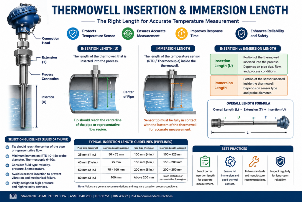
The insertion length is the length of the thermowell that extends inside the process and is exposed to the process fluid. It is measured from the process connection (or seating plane) to the closed tip of the thermowell. This dimension is commonly represented by the letter U in thermowell drawings.
Insertion length is one of the most important parameters in thermowell selection because it determines how deeply the temperature sensor reaches into the process. A properly selected insertion length ensures that the sensing tip is surrounded by the process fluid, allowing it to measure the actual process temperature rather than being influenced by the temperature of the pipe or vessel wall.
For example, in a water pipeline, a thermowell with a short insertion length keeps the sensing tip near the pipe wall, which is often cooler than the flowing water due to heat loss to the surroundings. This can cause the sensor to read a lower temperature than the actual process temperature. Extending the thermowell so the sensing tip is closer to the center of the flow improves measurement accuracy.
Although a longer insertion length generally improves measurement accuracy, it should not be made longer than necessary. Excessive insertion increases the unsupported length of the thermowell inside the flowing fluid, making it more susceptible to flow-induced vibration and mechanical failure. Therefore, engineers select an insertion length that provides accurate temperature measurement while maintaining the mechanical integrity of the thermowell.
Thermowell Immersion Length Chart
| Temperature Sensor Diameter | Minimum Recommended Immersion Length (RTD) | Minimum Recommended Immersion Length (Thermocouple) |
|---|---|---|
| 3 mm | 30–45 mm | 18–30 mm |
| 4 mm | 40–60 mm | 24–40 mm |
| 6 mm | 60–90 mm | 36–60 mm |
| 8 mm | 80–120 mm | 48–80 mm |
| 10 mm | 100–150 mm | 60–100 mm |
| 12 mm | 120–180 mm | 72–120 mm |
What is Thermowell Immersion Length?
While insertion length refers to the portion of the thermowell that extends into the process, immersion length refers to the portion of the temperature sensor that is effectively exposed to the process temperature.
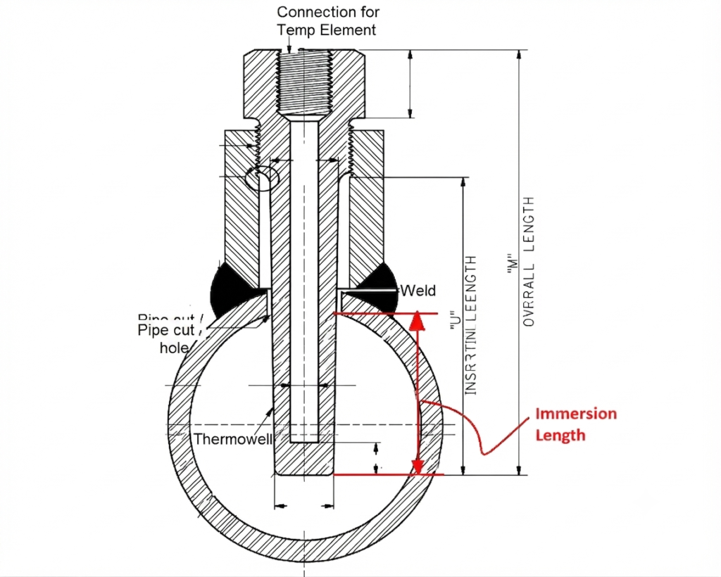
When an RTD or thermocouple is inserted into a thermowell, its sensing tip should reach the bottom of the thermowell. This ensures that the sensor receives the temperature conducted through the closed tip of the thermowell and accurately measures the process temperature. The length of the sensor that is exposed to this process temperature is known as the immersion length.
In most industrial installations, RTDs and thermocouples are spring-loaded, allowing the sensing tip to remain in firm contact with the bottom of the thermowell. As a result, the immersion length is almost equal to the thermowell’s insertion length. However, if the sensor is shorter than the thermowell or does not fully reach the bottom, an air gap is created between the sensor tip and the thermowell tip. Since air is a poor conductor of heat, this gap slows down heat transfer and can reduce measurement accuracy.
Insertion Length vs. Immersion Length
Although insertion length and immersion length are closely related, they refer to different parts of a temperature measurement assembly. The insertion length is associated with the thermowell, while the immersion length is associated with the temperature sensor. In most industrial applications, both lengths are nearly equal because the sensing tip reaches the bottom of the thermowell. However, they should not be considered the same.
The key differences are:
- Definition:
Insertion length is the length of the thermowell that extends inside the process, whereas immersion length is the length of the temperature sensor inserted into the thermowell so that its sensing element reaches the process temperature. - Associated Component:
Insertion length is a dimension of the thermowell, while immersion length is a dimension of the RTD, thermocouple, or other temperature sensor. - Purpose:
Insertion length determines how deeply the thermowell projects into the process fluid, whereas immersion length ensures that the sensor is sufficiently immersed to measure the true process temperature accurately. - Depends On:
Insertion length depends on the thermowell design and installation, whereas immersion length depends on the sensor length and whether its sensing tip reaches the bottom of the thermowell. - Practical Relationship:
In a properly designed assembly with a spring-loaded sensor, the immersion length is usually equal to or very close to the insertion length because the sensor tip remains in contact with the closed end of the thermowell.
In simple terms, the thermowell determines how far the assembly extends into the process, while the sensor determines how effectively the process temperature is measured inside the thermowell.
Why is Correct Insertion Length Important?
Selecting the correct insertion length is essential for obtaining accurate and reliable temperature measurements. A thermowell that is too short or too long can affect both the measurement accuracy and the mechanical integrity of the assembly.
1. Improves Measurement Accuracy
The sensing tip should be positioned well within the flowing process fluid rather than close to the pipe or vessel wall. If the insertion length is too short, the thermowell tip may be influenced by the cooler or hotter wall temperature, causing the sensor to measure a value that differs from the actual process temperature.
2. Minimizes Heat Conduction Errors
The thermowell conducts heat not only from the process fluid but also from the surrounding metal of the pipe or vessel. A short insertion length increases the influence of this heat conduction, resulting in measurement errors. A properly selected insertion length ensures that the sensing tip is primarily affected by the process fluid.
3. Improves Sensor Response Time
A thermowell that is sufficiently immersed in the flowing fluid experiences better heat transfer. This allows the temperature sensor to respond more quickly to process temperature changes, which is especially important in applications requiring fast control and monitoring.
4. Prevents Flow-Induced Vibration
Although a longer insertion length generally improves measurement accuracy, it also increases the unsupported portion of the thermowell inside the flowing fluid. High flow velocities can cause the thermowell to vibrate continuously, leading to fatigue, cracking, or even complete failure. Therefore, the insertion length should be long enough for accurate measurement but not longer than necessary.
5. Ensures Compliance with Engineering Standards
In critical applications involving high pressure, high temperature, or high flow velocity, the selected insertion length should satisfy the requirements of standards such as ASME PTC 19.3 TW, which evaluates thermowell strength and resistance to flow-induced vibration.
Rules of Thumb for Selecting Thermowell Insertion Length
Although the exact insertion length depends on factors such as the process fluid, pipe size, flow velocity, and operating conditions, engineers often follow a few practical guidelines during thermowell selection. These rules provide a good starting point and are widely used in industrial applications.
1. Position the Sensing Tip in the Main Flow
The thermowell tip should extend into the main flow of the process fluid rather than remaining close to the pipe wall. In pipelines, the sensing tip should preferably reach the centerline of the pipe or slightly beyond, where the fluid is well mixed and the measured temperature best represents the actual process temperature.
2. Follow the Minimum Immersion Requirement
To ensure accurate heat transfer, the temperature sensor should be immersed by at least:
- RTD: 10-15 times the probe diameter
- Thermocouple: 6-10 times the probe diameter
For example, an RTD with an 8 mm probe diameter should have a minimum immersion of approximately 80-120 mm.
3. Consider the Process Fluid
Liquids generally transfer heat more efficiently than gases. As a result, gas applications often require a longer insertion length to achieve the same measurement accuracy.
4. Avoid Excessive Insertion Length
A longer insertion length may improve measurement accuracy, but it also increases the unsupported portion of the thermowell inside the flowing fluid. In high-velocity applications, excessive insertion can lead to flow-induced vibration and mechanical failure. Therefore, the thermowell should only be as long as required for accurate measurement.
5. Consider Pipe Size
Small-diameter pipes require shorter thermowells, whereas larger pipelines and vessels often require longer insertion lengths to ensure that the sensing tip reaches the representative process zone.
6. Verify the Design for Critical Applications
In applications involving high pressure, high temperature, or high flow velocity, the insertion length should be verified using applicable engineering standards, such as ASME PTC 19.3 TW, to ensure the thermowell can safely withstand flow-induced forces.
Thermowell Insertion Length Formula and Calculation
There is no universal formula to calculate the required thermowell insertion length. Instead, the insertion length is selected based on factors such as the pipe size, process fluid, sensor type, and installation requirements. However, the following dimensional relationships are commonly used when designing or specifying a thermowell.
1. Overall Length Relationship
The overall length of a thermowell is the sum of its extension length and insertion length.
Overall Length (L) = Extension Length (T) + Insertion Length (U)
Where:
- L = Overall length of the thermowell
- T = Extension length (outside the process)
- U = Insertion length (inside the process)
This relationship is used by manufacturers when specifying thermowell dimensions.
2. Selecting the Insertion Length
The required insertion length is not determined by a mathematical equation but by engineering guidelines. A commonly followed practice is to ensure that the sensing tip reaches the representative flow region.
For pipelines:
- The sensing tip should preferably reach the centerline of the pipe or slightly beyond.
- In large vessels or tanks, the thermowell should extend sufficiently into the process to avoid measuring the wall temperature.
Example 1: Pipeline Installation
A thermowell is to be installed in a 100 mm diameter water pipeline. To obtain an accurate temperature measurement, the sensing tip should reach approximately the center of the pipe.
Therefore,
Required insertion length = 100 mm
If the extension length is 120 mm, then:
Overall Length = 120 + 100 = 220 mm
The nearest standard thermowell length can then be selected from the manufacturer’s catalogue.
In practice, engineers also verify that the selected insertion length satisfies mechanical design requirements, especially in applications involving high flow velocities. For such cases, standards like ASME PTC 19.3 TW are used to evaluate thermowell strength and vibration resistance before finalizing the design.
Recommended Thermowell Insertion Length Guidelines
The exact insertion length of a thermowell depends on the application, process conditions, and manufacturer recommendations. However, the following guidelines are commonly followed in industrial installations:
- 25 mm (1 in.) Pipe: A thermowell insertion length of 50-75 mm is generally sufficient, as the sensing tip can easily reach the main flow region.
- 40 mm (1½ in.) Pipe: An insertion length of approximately 75 mm provides adequate immersion for accurate temperature measurement.
- 50 mm (2 in.) Pipe: A thermowell with an insertion length of 75-100 mm is typically recommended to ensure the sensing tip is positioned away from the pipe wall.
- 80 mm (3 in.) Pipe: An insertion length of around 100 mm is commonly used to place the sensing tip near the center of the pipeline.
- 100 mm (4 in.) Pipe: A thermowell insertion length of 100-125 mm generally provides accurate temperature measurement while maintaining good mechanical stability.
- 150 mm (6 in.) Pipe: An insertion length of 150-200 mm is typically selected so that the sensing tip reaches the representative flow region.
- 200 mm (8 in.) Pipe and Larger: The insertion length should be selected so that the sensing tip reaches the pipe centerline or the representative process flow region. Standard thermowell lengths of 200-250 mm or longer may be used depending on the application.
Relevant Standards
The design, selection, and installation of thermowells are governed by several international standards to ensure accurate temperature measurement, mechanical reliability, and safe operation under various process conditions. The most commonly referenced standards are:
- ASME PTC 19.3 TW (Performance Test Code): This is the most widely used standard for thermowell design. It provides methods for evaluating thermowell strength, wake frequency, resonance, and flow-induced vibration, helping engineers ensure that a thermowell can safely withstand the operating conditions.
- ASME B40.200 – Thermowells for Temperature Instruments: This standard specifies the dimensional requirements, materials, construction, and general design considerations for industrial thermowells used with temperature measuring instruments.
- IEC 60751: This standard defines the performance characteristics, accuracy classes, temperature ranges, and tolerance requirements for platinum Resistance Temperature Detectors (RTDs), which are commonly installed inside thermowells.
- DIN 43772: A widely recognized German standard that specifies standardized thermowell dimensions and constructions. Although many manufacturers now use their own designs, DIN 43772 is still commonly referenced for dimensional compatibility.
- ISA Recommended Practices: The International Society of Automation (ISA) publishes recommended practices covering the selection, installation, and application of industrial temperature measurement devices to improve measurement accuracy and long-term reliability.
Conclusion
Selecting the correct thermowell insertion length and immersion length is essential for accurate, reliable, and fast temperature measurement in industrial applications. The insertion length determines how far the thermowell extends into the process fluid, while the immersion length ensures that the RTD or thermocouple sensing element is positioned correctly to measure the true process temperature.
A properly designed thermowell assembly reduces heat conduction errors, improves sensor response time, protects the temperature sensor from harsh process conditions, and extends its service life. When selecting the insertion length, engineers should consider factors such as pipe size, process fluid, flow velocity, operating temperature, pressure, and nozzle length. The sensing tip should be positioned in the representative process zone while avoiding excessive thermowell vibration and mechanical stress.
General rules of thumb are suitable for many standard applications, but they should not replace engineering verification in critical services. High-pressure, high-temperature, or high-velocity applications should be evaluated using applicable standards such as ASME PTC 19.3 TW, ASME B40.200, and IEC 60751, along with the thermowell manufacturer’s recommendations.
By understanding the concepts, differences, calculation methods, recommended insertion lengths, design considerations, and applicable standards, engineers can select the optimum thermowell configuration for accurate temperature measurement, safe operation, and long-term reliability.
Read Next: