An Orifice Meter is a differential-pressure flow-measuring device used to determine the flow rate of liquids, gases, and steam through a pipe. It works by placing a thin orifice plate with a precisely machined opening inside the pipeline. As fluid passes through the opening, its velocity increases and its pressure decreases. The resulting pressure difference is measured and used to calculate the flow rate.
Orifice meters are widely used in process industries, power plants, oil and gas facilities, chemical plants, water systems, and other industrial applications because they are simple, compact, and relatively inexpensive.
What Is an Orifice Meter?
An Orifice Meter is a type of differential-pressure flow meter used to measure the flow rate of a fluid in a closed pipeline.
The basic arrangement consists of an orifice plate installed between pipe flanges and pressure taps located upstream and downstream of the plate. When fluid flows through the smaller opening in the plate, its velocity increases while its static pressure decreases.
The pressure difference across the orifice is related to the flow rate. A differential-pressure transmitter can measure this pressure difference, allowing the flow rate to be calculated.
The basic relationship is:
where:
- = volumetric flow rate
- = differential pressure across the orifice
Thus, a larger pressure difference generally indicates a higher flow rate.
Orifice Meter Construction or Parts
An Orifice Meter consists of several components that work together to create a controlled pressure drop and measure the flow rate of fluid through a pipeline. The main parts include the inlet section, orifice plate, flow conditioner, outlet section, pressure taps, differential-pressure transmitter, impulse lines, flanges, and gaskets.
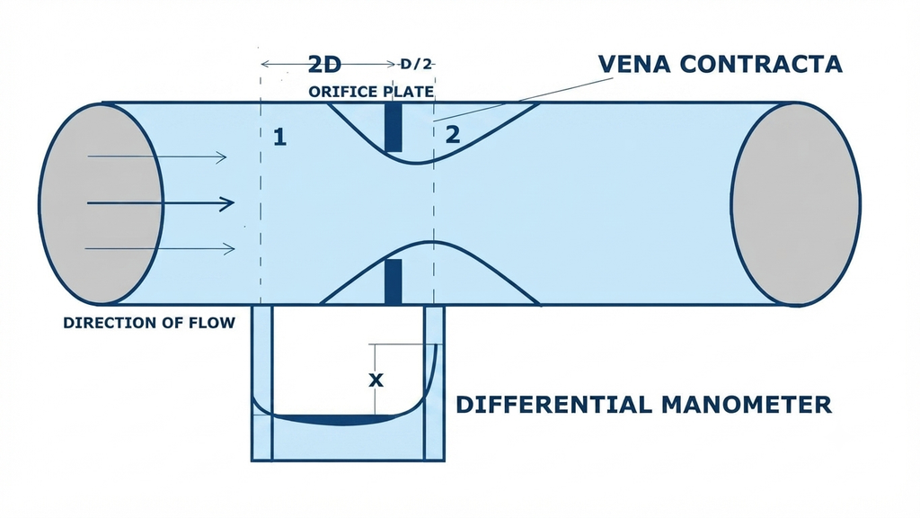
The major parts of an Orifice Meter are explained below.
1. Inlet Section
The inlet section is the portion of the pipeline through which the fluid enters the Orifice Meter. It provides a passage for the fluid before it reaches the orifice plate.
A sufficiently long and properly aligned inlet section helps establish a stable flow profile before the fluid reaches the restriction. Elbows, valves, pumps, and other disturbances close to the orifice can affect the flow profile and introduce measurement errors.
2. Orifice Plate
The orifice plate is the main flow-measuring element of an Orifice Meter. It is a thin metal plate with a precisely machined opening installed across the pipeline.
When fluid passes through the smaller opening, its velocity increases and its static pressure decreases. This creates the differential pressure required to determine the flow rate.
For a typical concentric orifice plate, the bore is located at the center of the plate.
The diameter ratio is defined as:
where:
- = orifice bore diameter
- = internal pipe diameter
The diameter ratio is an important parameter in Orifice Meter sizing and flow calculation.
3. Flow Conditioner
A flow conditioner may be installed upstream of the orifice plate to improve the flow profile before the fluid reaches the measurement section.
Upstream pipe fittings such as bends, valves, reducers, and tees can produce swirling or asymmetric flow. A properly selected flow conditioner helps reduce these disturbances and produces a more uniform velocity profile.
However, a flow conditioner is not necessarily a separate component in every Orifice Meter installation. Its use depends on the piping arrangement, applicable measurement standard, and required measurement performance.
4. Outlet Section
The outlet section is the part of the pipeline located downstream of the orifice plate. After passing through the restriction, the fluid continues through this section while the pressure gradually recovers from the minimum-pressure region.
The downstream pressure is measured at the appropriate pressure tap and is used together with the upstream pressure to determine the differential pressure.
5. Pressure Taps
Pressure taps are provided at specified locations upstream and downstream of the orifice plate.
The upstream tap senses the pressure , while the downstream tap senses . The differential pressure is:
This pressure difference is the primary measurement used to calculate the flow rate.
The location and type of pressure taps are important because different tap arrangements can produce different measurement characteristics.
6. Differential-Pressure Transmitter
A differential-pressure (DP) transmitter measures the pressure difference between the upstream and downstream pressure taps.
The transmitter receives the two pressure signals and produces an output proportional to the differential pressure. In an industrial measurement system, this signal can be sent to a flow indicator, PLC, DCS, or other control system.
Because flow is approximately proportional to the square root of differential pressure, square-root extraction is commonly applied:
7. Impulse Lines
Impulse lines connect the pressure taps on the pipeline to the differential-pressure transmitter.
They carry the sensed process pressure from the upstream and downstream sides of the orifice plate to the transmitter. Proper routing, installation, and maintenance of impulse lines are essential because blockages, leakage, condensation, or incorrect elevation arrangements can affect the pressure measurement.
8. Pipe Flanges
Flanges are used to connect the orifice plate assembly to the pipeline and hold the plate securely in position.
They also provide a convenient arrangement for inspection, removal, and replacement of the orifice plate during maintenance.
9. Gaskets
Gaskets are installed between mating flange surfaces to prevent fluid leakage.
The gasket should be compatible with the process fluid, pressure, and temperature. Incorrect gasket installation or protrusion into the flow path can disturb the flow and affect measurement accuracy.
10. Flow Pipe or Metering Section
The flow pipe provides the passage through which the measured fluid travels. The internal diameter of the pipe is an important parameter because it is used with the orifice bore diameter to determine the diameter ratio.
The pipe should be properly aligned and maintained in accordance with the applicable flow-measurement requirements.
Orifice Meter Parts at a Glance
| Part | Function |
| Inlet section | Allows fluid to enter the metering section |
| Orifice plate | Creates the controlled restriction and pressure difference |
| Flow conditioner | Helps improve the upstream flow profile when required |
| Outlet section | Carries fluid downstream of the orifice plate |
| Pressure taps | Sense upstream and downstream pressure |
| DP transmitter | Measures differential pressure |
| Impulse lines | Connect pressure taps to the transmitter |
| Pipe flanges | Hold and connect the orifice plate assembly |
| Gaskets | Prevent leakage at flange connections |
| Flow pipe | Provides the passage for the fluid |
The orifice plate, pressure taps, and differential-pressure measurement system form the core of an Orifice Meter. The inlet and outlet piping, along with proper flow conditioning and installation, help ensure that the pressure difference represents the actual flow conditions accurately.
Working Principle of Orifice Meter
The Orifice Meter works on the principles of Bernoulli’s equation and conservation of mass. It measures fluid flow by creating a restriction in the pipeline and measuring the resulting pressure difference.
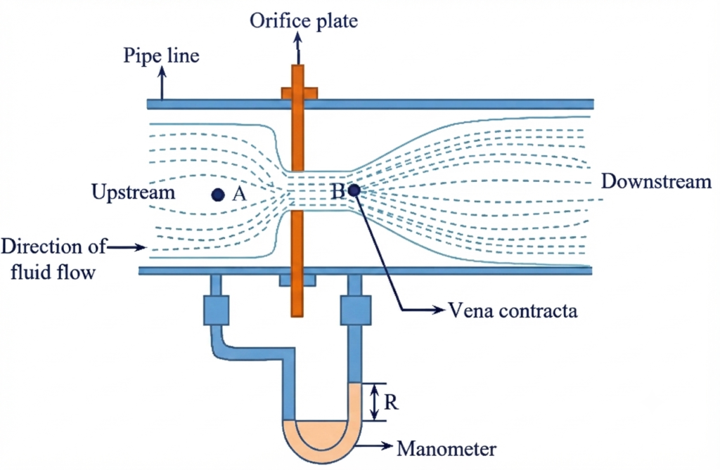
When fluid flows through the orifice plate, the available flow area decreases. According to the continuity principle, the fluid velocity increases as it passes through the smaller opening. At the same time, Bernoulli’s principle indicates that an increase in fluid velocity is accompanied by a decrease in static pressure.
The pressure upstream of the orifice plate is relatively high, while the pressure downstream is lower. These pressures are sensed through pressure taps installed at suitable locations around the orifice plate.
The differential pressure is:
where:
P1= upstream pressureP2= downstream pressure- = differential pressure across the orifice
The differential-pressure transmitter measures this pressure difference and sends the flow signal to the control or monitoring system. Since the flow rate is approximately proportional to the square root of the differential pressure, the relationship can be expressed as:
Working Steps of an Orifice Meter
The operation of an orifice meter can be summarized as follows:
- Fluid enters the metering section through the upstream pipe.
- The fluid approaches the orifice plate with a relatively high static pressure.
- The orifice plate restricts the available flow area.
- Fluid velocity increases as it passes through the orifice opening.
- Static pressure decreases because of the increase in velocity and the associated flow losses.
- Upstream and downstream pressure taps sense the pressure at the selected locations.
- The differential-pressure transmitter measures the pressure difference.
- The flow rate is calculated from the measured differential pressure using the appropriate orifice-meter equation.
Thus, an orifice meter converts fluid flow into a measurable differential pressure, which can then be used to determine the flow rate.
Orifice Meter Diagram
A simplified arrangement of an orifice flow meter is shown conceptually below:
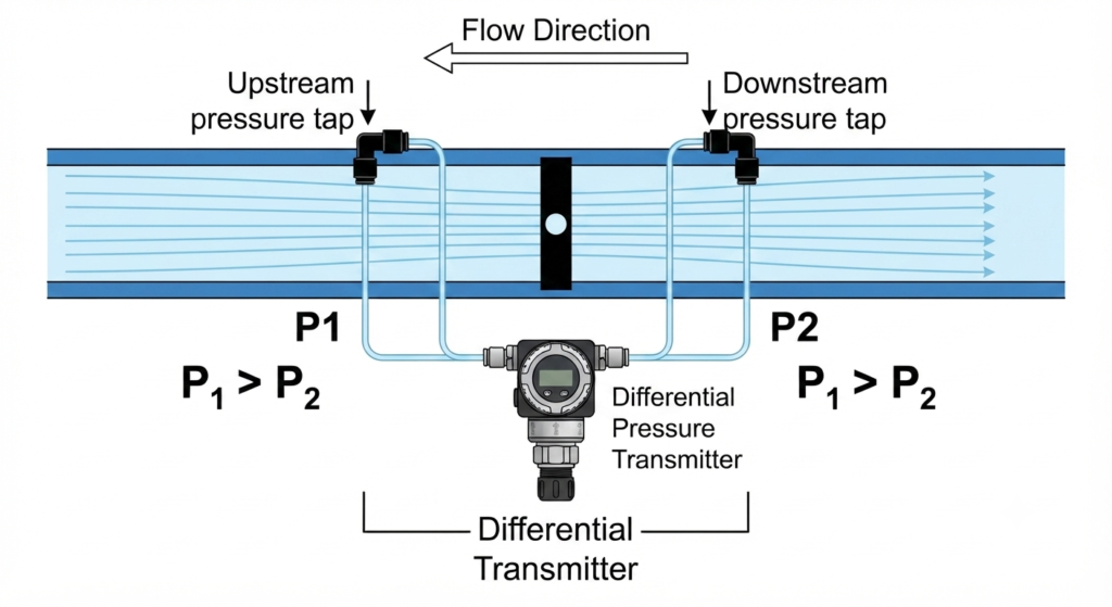
The orifice plate produces a restriction in the pipe. The upstream pressure is higher than the downstream pressure , and the difference between these pressures is used to determine the flow rate.
Types of Orifice Plates
Orifice plates can be classified according to the shape and position of the opening.
1. Concentric Orifice Plate
A concentric orifice plate has a circular hole located at the center of the plate.
It is the most common type and is suitable for many liquid, gas, and steam-flow applications.
2. Eccentric Orifice Plate
In an eccentric orifice plate, the opening is offset from the center.
It can be useful when the fluid contains suspended solids or when it is desirable to reduce the accumulation of liquid or solids near the restriction.
3. Segmental Orifice Plate
A segmental orifice has a segment-shaped opening.
It is particularly useful for fluids containing suspended solids, gases carrying liquids, or applications where clogging could be a concern.
Hydraulic Coefficients of an Orifice Meter
The performance of an orifice meter is described using several hydraulic coefficients. These coefficients help relate the actual flow behavior to the ideal conditions assumed in theoretical calculations.
The four important coefficients associated with an orifice meter are:
- Coefficient of Contraction
- Coefficient of Velocity
- Coefficient of Resistance
- Coefficient of Discharge
Coefficient of Contraction
The coefficient of contraction represents the reduction in jet area as the fluid passes through the orifice. It is defined as the ratio of the cross-sectional area of the jet at the vena contracta to the area of the orifice opening.
where:
Cc= coefficient of contractionAc= area of the jet at the vena contractaAo= area of the orifice opening
Coefficient of Velocity
The coefficient of velocity accounts for the difference between the actual velocity of the jet and its theoretical velocity at the vena contracta.
It is defined as the ratio of actual jet velocity to theoretical jet velocity.
where:
Cv= coefficient of velocityVactual= actual velocity of the jetVtheoretical= theoretical velocity of the jet
Coefficient of Resistance
The coefficient of resistance indicates the energy loss caused by the restriction and associated flow effects as the fluid passes through the orifice.
It is related to the head loss produced by the orifice and can be expressed as the ratio of the head loss to the available velocity head.
where:
K= coefficient of resistancehL= head loss due to the orificeV= reference fluid velocityg= acceleration due to gravity
Coefficient of Discharge
The coefficient of discharge accounts for the difference between the actual discharge and the theoretical discharge predicted by the ideal-flow equation.
It is defined as:
where:
Cd= coefficient of dischargeQactual= actual discharge through the orificeQtheoretical= theoretical discharge
For an orifice meter, the coefficient of discharge is particularly important because it incorporates the effects of contraction, velocity variation, and other real-flow effects that are not fully represented by the ideal theoretical equation.
Orifice Meter Discharge Formula
For an ideal incompressible flow, the theoretical discharge through an orifice can be expressed as:
where:
- = theoretical flow rate
- = area of orifice opening
- = pressure difference
- = fluid density
The area of the orifice opening is:
Therefore:
The actual discharge is lower than the theoretical discharge because of friction, contraction, and other flow effects.
Therefore:
This is one of the most commonly used forms of the orifice meter discharge formula.
Orifice Flow Meter Formula
The general orifice flow meter formula for an incompressible fluid is:
Since:
the equation can also be written as:
where:
- = actual volumetric flow rate in
- = coefficient of discharge
- = orifice diameter in m
- = pipe diameter in m
- = differential pressure in Pa
- = fluid density in
For a given installation, the exact flow calculation may require additional correction factors depending on the fluid, Reynolds number, pressure-tap arrangement, pipe geometry, and applicable measurement standard.
Derivation of Orifice Meter Formula
Consider a pipe of diameter containing an orifice plate with an opening of diameter .
Let:
- = pipe cross-sectional area
- = orifice area
- = velocity upstream
- = velocity through the restriction
- = upstream pressure
- = downstream pressure
From the continuity equation:
Therefore:
and
For ideal flow, Bernoulli’s equation gives:
Rearranging:
Therefore:
Using the continuity relationship and the area ratio, the theoretical flow rate becomes:
Considering actual flow effects through the coefficient of discharge:
Since:
we obtain:
Orifice Meter Calculation
An orifice meter calculation requires several parameters.
Typically, you need:
- Pipe diameter
- Orifice diameter
- Differential pressure
- Fluid density
- Coefficient of discharge
1. Determine the Diameter Ratio
2. Find the Orifice Area
3. Calculate Flow Rate
The resulting value gives the volumetric flow rate when consistent SI units are used.
Sample Problem With Solution
Consider an orifice meter installed in a water pipeline with the following data:
- Pipe diameter mm
- Orifice diameter mm
- Differential pressure kPa
- Water density kg/m³
- Coefficient of discharge
1. Convert Diameters
2. Calculate Diameter Ratio
3. Calculate Orifice Area
4. Calculate Flow Rate
The differential pressure is:
Using the orifice flow meter formula:
Therefore:
or approximately:
This example demonstrates the basic orifice meter calculation. In an actual industrial installation, the calculation should use the appropriate standardized equation and correction factors for the particular service.
Pressure Loss in an Orifice Meter
One important limitation of an Orifice Meter is its permanent pressure loss.
The pressure decreases as fluid passes through the restriction. Some of this pressure is recovered downstream, but a portion is permanently lost because of turbulence and friction.
This permanent pressure loss means that an orifice meter generally consumes more pumping or compression energy than a Venturi meter for the same service.
Therefore, pressure loss should be considered when selecting an orifice meter for an industrial process.
Orifice Meter Specifications
The specifications of an Orifice Meter depend on the pipe size, fluid being measured, operating conditions, orifice plate material, and applicable design standards. Important specifications generally include the orifice bore, pipe diameter, pressure rating, temperature range, and diameter ratio.
Typical considerations include:
| Parameter | Typical Specification or Consideration |
| Orifice bore diameter | Selected according to the required flow range and differential pressure |
| Pipe diameter | Depends on the size of the process pipeline |
| Diameter ratio (β) | Commonly selected within the applicable design-standard range |
| Operating temperature | Depends on the plate material, gaskets, fittings, and process conditions |
| Operating pressure | Determined by the pressure rating of the flanges, plate assembly, and piping system |
| Orifice plate material | Selected according to fluid properties, temperature, pressure, and corrosion requirements |
| Pressure tapping | Selected according to the applicable orifice-meter design standard |
| Differential pressure | Sized according to the required flow range and allowable permanent pressure loss |
For many industrial applications, the orifice plate is designed and sized according to recognized flow-measurement standards. Therefore, values such as maximum operating pressure and temperature should not be treated as fixed limits for every orifice flow meter. The final specification should always be established from the process conditions and the selected design standard.
Advantages of Orifice Meter
An Orifice Meter offers several advantages:
- Simple construction
- Low initial cost
- No moving parts
- Compact design
- Easy installation
- Suitable for liquids, gases, and steam
- Easy replacement of the orifice plate
- Suitable for high-pressure applications
- Can provide good repeatability when properly designed and installed
- Widely accepted for industrial flow measurement
Disadvantages of Orifice Meter
Despite its simplicity, an Orifice Meter has some limitations:
- Causes permanent pressure loss
- Requires relatively straight pipe lengths
- Accuracy can be affected by upstream disturbances
- Orifice plates can wear over time
- The opening can become damaged or contaminated
- Flow rangeability is limited compared with some modern flow meters
- Differential-pressure measurement requires additional instrumentation
- Small pressure differences can become difficult to measure accurately at very low flow rates
- Improper installation can produce significant measurement errors
Applications of Orifice Meter
Orifice meters are used for flow measurement in a wide range of industries and process systems, including:
- Power Plants: Measuring water, steam, compressed air, fuel gas, and other process flows.
- Oil and Gas Industry: Measuring gas and liquid flows in process, transmission, and utility systems.
- Chemical Plants: Measuring process fluids, gases, and utility streams.
- Water Treatment Plants: Measuring water flow through pipelines and treatment systems.
- Compressed-Air Systems: Monitoring compressed-air consumption and distribution.
- Steam Systems: Measuring steam flow using an orifice plate and differential-pressure measurement system.
- Process Industries: Measuring general-purpose liquid and gas flows where differential-pressure flow measurement is suitable.
Orifice Meter Applications in Industrial Instrumentation
In industrial instrumentation, the orifice meter forms part of a flow measurement and control system. The orifice plate creates a differential pressure, while a differential-pressure transmitter measures this pressure difference and converts it into an electrical signal.
The signal is then sent to a PLC, DCS, flow indicator, or other control system for monitoring, display, recording, or control.
A typical instrumentation arrangement is:
↓
Orifice Plate
↓
Differential Pressure
↓
DP Transmitter
↓
Flow Signal
↓
PLC / DCS / Flow Indicator
The control system can use square-root extraction to convert the measured differential pressure into a flow signal because flow is approximately proportional to the square root of differential pressure.
For example, if the differential pressure increases four times, the corresponding flow increases approximately two times, provided the fluid properties and other operating conditions remain constant.
Orifice Meter vs Venturi Meter
Both Orifice and Venturi meters use differential pressure to measure flow, but their construction and performance differ.
| Parameter | Orifice Meter | Venturi Meter |
| Construction | Thin plate with opening | Converging and diverging tube |
| Cost | Lower | Higher |
| Size | Compact | Larger |
| Installation | Relatively simple | Requires more space |
| Pressure loss | Higher | Lower |
| Maintenance | Simple | More involved |
| Moving parts | None | None |
| Accuracy | Good when properly installed | Generally higher |
| Replacement | Plate can be replaced easily | Whole meter section is more substantial |
| Application | General industrial flow measurement | Applications where low pressure loss is important |
The choice depends on factors such as accuracy, available space, pressure-loss requirements, operating conditions, maintenance requirements, and cost.
Precautions for Orifice Meter Installation
Proper installation helps the Orifice Meter provide accurate and reliable flow measurements. Follow these precautions:
- Maintain proper pipe alignment: Align the pipe and orifice plate correctly to avoid disturbing the flow profile and introducing measurement errors.
- Use the correct orifice plate: Select the plate bore, thickness, material, and geometry according to the fluid, operating conditions, and measurement requirements.
- Provide adequate straight pipe length: Maintain the required straight pipe length upstream and downstream of the orifice plate according to the applicable flow-measurement standard.
- Keep the orifice opening clean: Remove deposits, corrosion, and other obstructions that could alter the effective bore and affect flow measurement.
- Check pressure tappings: Install the pressure taps correctly and keep the taps and impulse lines free from blockage or leakage.
- Check for leakage: Properly tighten and seal flange joints, pressure connections, and impulse-line connections to prevent fluid leakage.
- Consider fluid properties: Account for density, viscosity, temperature, pressure, and compressibility when sizing the orifice meter and calculating the flow rate.
- Inspect the plate periodically: Check the orifice plate for erosion, corrosion, deformation, and deposits, particularly when measuring corrosive, abrasive, or contaminated fluids.
Orifice Meter Flow Measurement Accuracy
The accuracy of an Orifice Meter depends not only on the equation but also on the quality of the installation.
Important factors include:
- Correct plate dimensions
- Correct bore diameter
- Proper edge condition
- Correct pressure-tap location
- Adequate straight pipe length
- Stable flow profile
- Correct differential-pressure measurement
- Proper density and process-property data
- Correct transmitter configuration
- Appropriate calibration
For critical custody-transfer or high-accuracy applications, standardized calculation procedures should be followed rather than relying on a simplified equation alone.
Conclusion
An Orifice Meter is one of the simplest and most widely used differential-pressure flow-measuring devices. It uses an orifice plate to create a controlled restriction in a pipeline and measures the resulting pressure difference to determine fluid flow.
The orifice meter discharge formula relates flow rate to differential pressure, fluid density, orifice diameter, pipe diameter, and coefficient of discharge. Proper plate design, pressure-tap arrangement, installation, and maintenance are essential for obtaining reliable measurements.
Because of its simple construction, low cost, compact size, and wide industrial applicability, the Orifice Meter remains an important flow-measurement method in power plants, process industries, water systems, chemical plants, and oil and gas facilities.
Frequently Asked Questions
An Orifice Meter is a differential-pressure flow meter that measures fluid flow by creating a pressure difference across an orifice plate.
The orifice plate creates the restriction in the pipeline, while the orifice meter refers to the complete flow-measuring system, including the orifice plate, pressure taps, and differential-pressure measurement equipment.
An Orifice Meter works mainly on the principles of Bernoulli’s equation and continuity. The restriction increases fluid velocity and produces a measurable pressure drop.
Orifice meters measure the flow of liquids, gases, and steam when engineers properly design and install the meter for the specific service.
The restriction creates turbulence and energy dissipation in the flowing fluid. Consequently, only part of the pressure drop is recovered downstream.
Read Next:
- Basics of Restriction Orifice (RO) – Types, Applications, and Standards
- Orifice Beta Ratio: Definition, Importance, and Why It Is Limited Between 0.3 to 0.7
- Basics of Orifice Plates
- Orifice Plate Tapping – Types of Orifice Plate Taps Explained
- Coriolis Mass Flow Meter Working Principle
- Orifice Discharge Coefficient: Formula, Meaning, Factors and Calculation