A capacitance differential pressure transmitter is an industrial instrument that measures the pressure difference between two points using changes in electrical capacitance. It converts the measured pressure difference into an electrical signal that can be used for process monitoring, indication, and automatic control.
This type of transmitter is widely used in industrial instrumentation because capacitive sensing can provide high sensitivity, good measurement stability, and reliable performance across a range of process conditions.
The core of the instrument is a differential capacitive sensing cell. It typically contains a flexible metal sensing diaphragm positioned between two stationary electrodes. When the pressures applied to the two sides differ, the diaphragm deflects, changing the capacitance of the two sensing elements. Electronic circuitry detects this change and converts it into a signal proportional to the applied differential pressure.
In this article, we will examine the working principle, internal construction, sensing diaphragm, isolation diaphragms, fill fluid, overpressure protection, and industrial applications of a capacitance differential pressure transmitter.
What Is a Capacitance Differential Pressure Transmitter?
A capacitance differential pressure transmitter is a pressure-measuring instrument that uses the electrical capacitance between conductive surfaces to determine the pressure difference between two process connections.
Unlike a conventional pressure transmitter that measures pressure relative to a specified reference, a differential pressure transmitter has two pressure inputs. These are commonly identified as the high-pressure (HP) and low-pressure (LP) connections.
The measured differential pressure is expressed as:
Where:
- = Differential pressure
- = Pressure applied to the high-pressure side
- = Pressure applied to the low-pressure side
The transmitter converts this pressure difference into a measurable electrical output. Depending on the instrument design, the output may be a 4–20 mA signal, a digital communication signal, or both.
Typical applications include flow measurement, liquid-level measurement, filter monitoring, and pressure-drop measurement across industrial equipment.
Working Principle of a Capacitance Differential Pressure Transmitter
The working principle is based on the relationship between pressure-induced diaphragm displacement and electrical capacitance.
A typical metal capacitive sensing element consists of three conductive surfaces: two stationary electrodes and one flexible sensing diaphragm positioned between them. This arrangement forms two capacitors.
When equal pressures act on the two sides, the sensing diaphragm remains close to its balanced position. The two capacitances are approximately equal under balanced conditions.
When the pressure on one side becomes higher than the pressure on the other, the resulting force deflects the sensing diaphragm toward the lower-pressure side. This movement changes the spacing between the diaphragm and the two electrodes.
As a result, one capacitance increases while the other decreases. The electronic circuit detects the difference between these capacitances and converts it into a signal representing differential pressure.
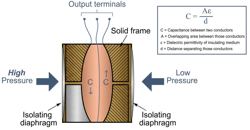
The process can be explained in five steps.
Step 1: Apply Pressure to the Two Process Connections
The HP and LP ports receive pressure from the two measurement points. The difference between these pressures acts on the transmitter’s sensing assembly.
Step 2: Transfer Pressure Through the Isolation Diaphragms
In a typical filled-cell design, flexible isolation diaphragms separate the process fluid from the internal sensing mechanism. A compatible fill fluid transfers the applied pressure to the central sensing diaphragm.
Step 3: Deflect the Sensing Diaphragm
The difference in pressure creates a net force on the sensing diaphragm. Its displacement depends on the applied differential pressure and the mechanical characteristics of the diaphragm.
The relationship between pressure, force, and effective diaphragm area is:
Where:
- = Resultant force
- = Applied differential pressure
- = Effective diaphragm area
For a given effective area, a greater pressure difference produces a greater force.
Step 4: Detect the Change in Capacitance
The sensing diaphragm moves relative to the stationary electrodes. This changes the spacing between the conductive surfaces and therefore changes the capacitances of the two sensing elements.
The transmitter’s capacitance-detection circuit measures the resulting electrical change.
Step 5: Convert the Measurement Into an Output Signal
The electronic circuitry processes the capacitance measurement and converts it into an output representing differential pressure.
The signal can then be transmitted to a PLC, DCS, indicator, recorder, or other compatible control system.
Construction of a Metal Capacitance Differential Pressure Transmitter
A typical metal capacitive differential pressure transmitter uses a specially designed measuring cell containing a sensing diaphragm, two stationary electrodes, isolation diaphragms, and an internal fill fluid.
The principal components are described below.
1. Sensing Diaphragm
The sensing diaphragm is the central mechanical element of the capacitive measuring cell. It is usually a thin, precision-manufactured metal diaphragm designed to deflect predictably under an applied differential pressure.
The diaphragm also acts as a movable conductive plate in the capacitive sensing arrangement.
When the diaphragm moves, the distance between it and each stationary electrode changes. These changes produce opposite variations in the two capacitances, enabling the electronics to determine the applied pressure difference.
The diaphragm must be sufficiently sensitive to detect small pressure changes while remaining within its specified mechanical limits.
2. Stationary Capacitor Electrodes
Two stationary conductive surfaces are positioned on opposite sides of the sensing diaphragm. Together with the diaphragm, they form a complementary pair of capacitors.
For a simplified parallel-plate capacitor, capacitance is expressed as:
Where:
- = Capacitance
- = Permittivity of the insulating medium
- = Effective overlapping plate area
- = Distance between the conductive surfaces
If the plate area and permittivity remain approximately constant, capacitance increases as the separation decreases.
Consequently, diaphragm movement increases one capacitance and decreases the other. Measuring this differential change provides a sensitive method of detecting diaphragm displacement.
Actual transmitter sensing cells may use more complex electrode geometries, so the equation represents the basic principle rather than every design detail.
3. Isolation Diaphragms
Isolation diaphragms separate the process fluid from the internal sensing cell. They are generally designed to flex in response to changes in process pressure.
The pressure applied to each isolation diaphragm is transferred through the fill fluid to the sensing diaphragm.
These diaphragms help protect the internal sensing mechanism from direct exposure to corrosive, contaminated, or otherwise unsuitable process fluids, provided the selected materials are compatible with the application.
Isolation diaphragms also play an important role in limiting excessive movement during overpressure conditions in suitable transmitter designs.
4. Fill Fluid
A compatible liquid fill fluid occupies the internal spaces between the isolation diaphragms and the sensing cell. In some designs, it also fills capillary passages connecting remote diaphragm seals to the sensor.
The fill fluid performs several functions:
- Transfers pressure from the isolation diaphragms to the sensing diaphragm.
- Keeps the process fluid separated from the internal sensing components.
- Provides a consistent dielectric medium for the capacitive sensing arrangement.
- Helps enable overpressure protection when used with an appropriately designed mechanical stop.
The fill fluid must be selected according to the operating temperature, process requirements, and transmitter design.
Different fill fluids have different temperature characteristics. The permissible temperature limits must always be confirmed using the manufacturer’s datasheet for the specific instrument.
5. Sensor Housing and Measuring Cell
The measuring cell contains the capacitive sensing components and the associated internal structures.
The housing supports and protects the assembly while maintaining the required mechanical relationship between the sensing diaphragm and the stationary electrodes.
The arrangement may vary between traditional sensor designs and more compact coplanar constructions.
6. Electronic Circuit
The electronic circuit detects changes in capacitance and processes the resulting measurement.
In a typical design, an alternating-current excitation signal is used by the capacitance-detection circuit. The measured electrical response is processed to determine the differential capacitance and convert it into a usable pressure signal.
Additional electronics may provide temperature compensation, linearization, damping, diagnostics, and output-signal generation.
Differential Capacitance Measurement
The main feature of a metal capacitive differential pressure transmitter is that it measures the difference between two capacitances rather than relying solely on the absolute value of one capacitor.
The sensing diaphragm forms a movable plate between two stationary electrodes. When the diaphragm shifts from its balanced position, the two electrode gaps change in opposite directions.
The capacitances can be represented as:
Where (d_1) and (d_2) are the respective electrode gaps.
The difference between the two capacitances is:
The sign of this difference depends on the electrode assignment and the direction of diaphragm movement.
As differential pressure changes, the capacitance difference changes. The electronic circuit interprets this variation and calculates the corresponding pressure measurement.
This differential measurement approach allows the transmitter to detect small diaphragm movements and produce a useful pressure signal.
Role of Isolation Diaphragms in Overpressure Protection
Overpressure protection is an important feature of many modern differential pressure transmitters.
The sensing diaphragm is designed to move within a limited range. If excessive differential pressure forces it beyond its permitted displacement, the diaphragm may deform permanently or the sensor may be damaged.
To reduce this risk, certain transmitter designs use flexible isolation diaphragms together with a rigid supporting frame or mechanical stop.
When excessive pressure is applied to one side, the corresponding isolation diaphragm moves toward the supporting frame. At a specified displacement, it contacts the frame and cannot move significantly farther.
This limits the additional volume displacement transmitted through the fill fluid and helps protect the central sensing diaphragm from excessive movement.
The protection mechanism depends on the specific sensor construction and its rated pressure limits. It does not mean that the transmitter can withstand unlimited pressure.
Why Is Fill Fluid Important for Overpressure Protection?
The sensing diaphragm must remain free to move within the capacitive cell without contacting the surrounding conductive structure during normal measurement.
At the same time, effective overpressure protection may require an isolation diaphragm to contact a mechanical stop.
Using separate sensing and isolation diaphragms allows these functions to be handled by different components:
- The central sensing diaphragm provides sensitive capacitance measurement.
- The isolation diaphragms transfer process pressure and can work with mechanical stops to limit excessive movement.
- The fill fluid transmits pressure between the diaphragms while keeping the process fluid separate from the sensing cell.
This arrangement helps reconcile the need for sensitive, non-contact capacitive measurement with the need for mechanical protection against excessive pressure.
The actual protection capability must be verified against the manufacturer’s specifications.
Remote Diaphragm-Seal Differential Pressure Transmitters
Some differential pressure applications require remote diaphragm seals instead of conventional process connections mounted directly at the transmitter.
In this arrangement, process pressure acts on an isolation diaphragm at each measurement point. The pressure is transmitted to the sensing cell through fill-fluid-filled capillaries.
The sensing element measures the pressure difference conveyed by the two seal assemblies.
Remote diaphragm seals are useful when the process fluid is corrosive, viscous, prone to crystallization, contains suspended solids, or operates under conditions that make direct impulse-line connections unsuitable.
The fill fluid must be compatible with the expected operating temperature and the pressure-transmission requirements.
Coplanar Sensor Construction
Some modern differential pressure transmitters use a compact coplanar sensor arrangement. In these designs, the sensor assembly and process isolation diaphragms are positioned to reduce the overall size and provide a practical mounting arrangement.
Certain designs also help minimize the influence of stresses caused by process-flange bolts on the sensing element.
The actual degree of mechanical isolation depends on the transmitter construction. Installation torque and mounting requirements should therefore follow the manufacturer’s instructions.
Advantages of a Capacitance Differential Pressure Transmitter
Capacitive sensing offers several benefits when correctly applied.
1. High Sensitivity
A small change in diaphragm position can produce a measurable change in capacitance. This makes capacitive sensing suitable for applications that require the detection of relatively small pressure differences.
2. Good Measurement Stability
A properly designed and calibrated transmitter can provide stable measurements over its specified operating conditions.
Long-term performance still depends on sensor construction, temperature effects, installation, process conditions, and maintenance.
3. Reliable Industrial Operation
Metal sensing cells and suitable isolation diaphragms can provide robust service in demanding industrial environments when the instrument is correctly selected.
4. Process Isolation
Isolation diaphragms and fill fluid can keep corrosive or contaminated process fluids away from the internal sensing components.
This protection is effective only when the diaphragm materials, seals, and fill fluid are compatible with the process.
5. Overpressure Protection
Transmitter designs incorporating isolation diaphragms and mechanical stops can limit sensing-element displacement under specified overpressure conditions.
6. Versatile Applications
A differential capacitance sensing cell can be used in a variety of measurement systems, including flow, level, and pressure-drop monitoring.
Applications of Capacitance Differential Pressure Transmitters
Capacitance differential pressure transmitters are used in many process industries because one instrument design can support several measurement functions.
1. Flow Measurement
A DP transmitter can measure the pressure difference across an orifice plate, Venturi tube, or another suitable primary flow element.
For many conventional differential-pressure flow systems, flow rate is approximately proportional to the square root of differential pressure:
The transmitter or receiving control system must be configured appropriately to convert differential pressure into flow rate.
2. Liquid-Level Measurement
In a tank, the hydrostatic pressure produced by a liquid column is related to the liquid height:
A DP transmitter can use this pressure relationship to determine liquid level. Open tanks and closed, pressurized vessels require different pressure-reference arrangements.
Correct installation, range configuration, and compensation for density and fill-leg effects are important for accurate measurement.
3. Filter and Strainer Monitoring
The transmitter measures the pressure difference between the inlet and outlet of a filter or strainer.
A rising differential pressure may indicate the accumulation of contaminants or a restriction in the flow path. The measurement can be used to generate a maintenance alarm when the configured threshold is reached.
4. HVAC Systems
Differential pressure measurement is used in heating, ventilation, and air-conditioning systems to monitor air pressure differences, filter loading, and airflow when a suitable measurement arrangement is provided.
5. Chemical and Process Industries
Capacitance differential pressure transmitters can be used for process-flow, vessel-level, and pressure-drop measurements in chemical and other process industries.
Wetted materials and fill fluids must be selected according to the process medium and operating conditions.
6. Power Generation and Industrial Utilities
Applications include suitable steam, water, gas, and air flow measurements, as well as differential pressure monitoring across selected equipment.
The instrument’s pressure, temperature, and material ratings must be appropriate for the specific service.
Factors Affecting Measurement Performance
Although capacitive sensing can provide sensitive measurement, several factors can influence transmitter performance.
Temperature changes: Temperature can affect the sensing cell, fill fluid, and electronic components. Use an instrument rated for the expected process and ambient temperatures.
Incorrect installation: Unequal elevation effects, improperly routed impulse lines, or unsuitable mounting can introduce measurement errors.
Fill-fluid effects: Changes in fill-fluid properties or unsuitable fill-fluid selection can affect pressure transmission, especially in demanding temperature conditions.
Mechanical stress: Excessive or uneven mounting stress may affect some sensor designs. Follow the specified installation and tightening procedures.
Blocked impulse lines: Deposits, frozen liquid, or trapped gas can interfere with the pressure reaching the sensing element.
Incorrect range configuration: An incorrectly configured lower range value or upper range value can cause the output to disagree with the actual process measurement.
Overpressure: Pressure exceeding the instrument’s rated limits may cause damage even when an isolation diaphragm or mechanical stop is provided.
Regular inspection, correct installation, and calibration according to the maintenance schedule help maintain reliable measurement.
Conclusion
A capacitance differential pressure transmitter measures pressure difference by detecting changes in capacitance caused by the movement of a sensing diaphragm. Its central measuring cell generally contains two stationary electrodes and a movable conductive diaphragm that forms a pair of capacitors.
In many industrial designs, isolation diaphragms and an internal fill fluid transfer process pressure to the sensing element while protecting it from direct process-fluid contact. These components can also contribute to overpressure protection when combined with an appropriately designed mechanical stop.
The combination of capacitive sensing, pressure isolation, and electronic signal processing makes this technology suitable for flow measurement, liquid-level measurement, filter monitoring, and other industrial applications.
For reliable operation, select the transmitter according to its specified pressure and temperature limits, ensure compatibility with the process fluid, install it correctly, and follow the manufacturer’s requirements for calibration and maintenance.
Read Next:
- Transmitter: Types, Working Principle, and Examples
- SMART Transmitter: Working Principle, Components, Advantages
- Level Transmitter Calibration Procedure
- Level Transmitter: Types, Working Principle & Applications
- Differential Pressure Transmitter: Working Principle, Types
- Strain-Gauge Differential Pressure Transmitter: Working Principle, Diagram, Components, and Applications
- Piezoresistive Differential Pressure Transmitter: Working Principle, Diagram, Components, and Applications