A differential pressure transmitter (DP transmitter) measures the pressure difference between two points and converts it into an electrical signal for monitoring and process control. It is widely used in industries such as cement, power generation, oil and gas, chemical processing, water treatment, and pharmaceuticals.
A DP transmitter can measure fluid flow through an orifice plate, liquid level inside a closed tank, and pressure drop across a filter. It also helps operators identify abnormal process conditions before they affect plant performance.
In this guide, you will learn about the differential pressure transmitter working principle, internal construction, different sensor types, installation requirements, manifold connections, calibration procedures, troubleshooting methods, and industrial applications.
What Is Differential Pressure?
Differential pressure is the difference between the pressures measured at two different points in a system. It indicates how pressure changes as a fluid moves through a pipe, vessel, filter, or other process equipment.
The differential pressure formula is:
Where:
- = Differential pressure
- = Pressure at the high-pressure point
- = Pressure at the low-pressure point
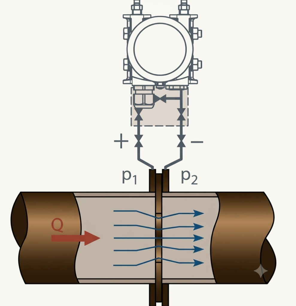
Example: Suppose the pressure at the inlet of a filter is 5 bar and the pressure at its outlet is 4.2 bar.
The pressure drop across the filter is 0.8 bar. If this value gradually increases during operation, it may indicate that the filter is becoming clogged.
Differential pressure is therefore an important parameter for monitoring equipment condition and process performance.
What Is a Differential Pressure Transmitter?
A differential pressure transmitter is an industrial instrument that senses the pressure difference between two process connections and converts the measured value into a proportional output signal.
The instrument generally has two pressure connections:
- High-pressure (HP) port: Connected to the higher-pressure side of the process.
- Low-pressure (LP) port: Connected to the lower-pressure side of the process.
The transmitter measures the pressure difference between these connections rather than measuring either pressure independently as its primary variable.
Modern DP transmitters commonly provide a 4–20 mA output, with options such as HART communication or digital fieldbus protocols, depending on the model.
The output can be connected to a PLC, DCS, indicator, recorder, or SCADA system for monitoring and control.
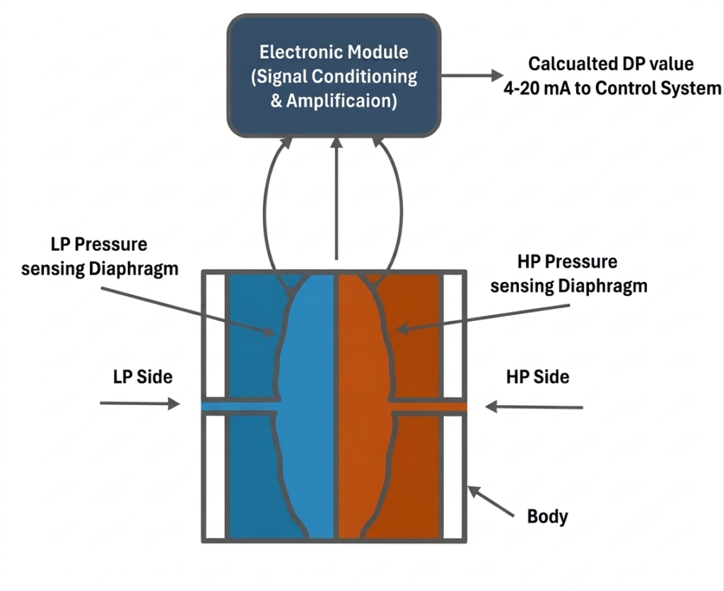
Block Diagram of a Differential Pressure Transmitter
Regardless of the sensing technology used, the basic working principle of a differential pressure transmitter can be represented by the following block diagram.
Main Functions of a DP Transmitter
A differential pressure transmitter can perform several measurement functions:
- Flow measurement: Determines flow rate using the pressure difference across a primary element.
- Level measurement: Measures liquid level in tanks and process vessels.
- Filter monitoring: Detects an increasing pressure drop caused by filter blockage.
- Pressure monitoring: Measures the difference between two process pressures.
- Equipment monitoring: Helps assess pressure losses across heat exchangers, strainers, and other equipment.
Working Principle of a Differential Pressure Transmitter
The differential pressure transmitter working principle is based on sensing the mechanical effect of a pressure difference and converting it into an electrical signal.
The process generally involves the following steps.
Step 1: Pressure Is Applied to the HP and LP Ports
The high-pressure and low-pressure connections receive pressure from two different points in the process. The pressure difference acts on the transmitter’s sensing assembly.
Step 2: The Sensing Diaphragm Responds
The pressure difference causes a small displacement or deformation of the sensing diaphragm. The magnitude of this response depends on the applied differential pressure and the design of the sensing element.
Step 3: The Sensor Converts the Response Into an Electrical Signal
Depending on the sensor technology, diaphragm movement or mechanical stress changes capacitance, resistance, inductance, or another measurable electrical property.
Step 4: Electronic Circuitry Processes the Signal
The transmitter’s electronic circuit processes the sensor signal and compensates for factors such as temperature effects and other specified measurement errors.
Step 5: The Transmitter Sends the Output
The processed measurement is converted into an output signal that represents the measured differential pressure. A typical industrial transmitter uses a 4–20 mA signal.
The signal is then received by the control system, where it can be displayed, recorded, or used in an automatic control loop.
Important: The exact sensing mechanism varies by transmitter design. Not every DP transmitter uses the same diaphragm arrangement or sensing technology.
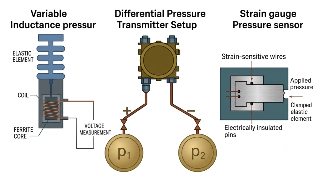
Internal Construction of a Differential Pressure Transmitter
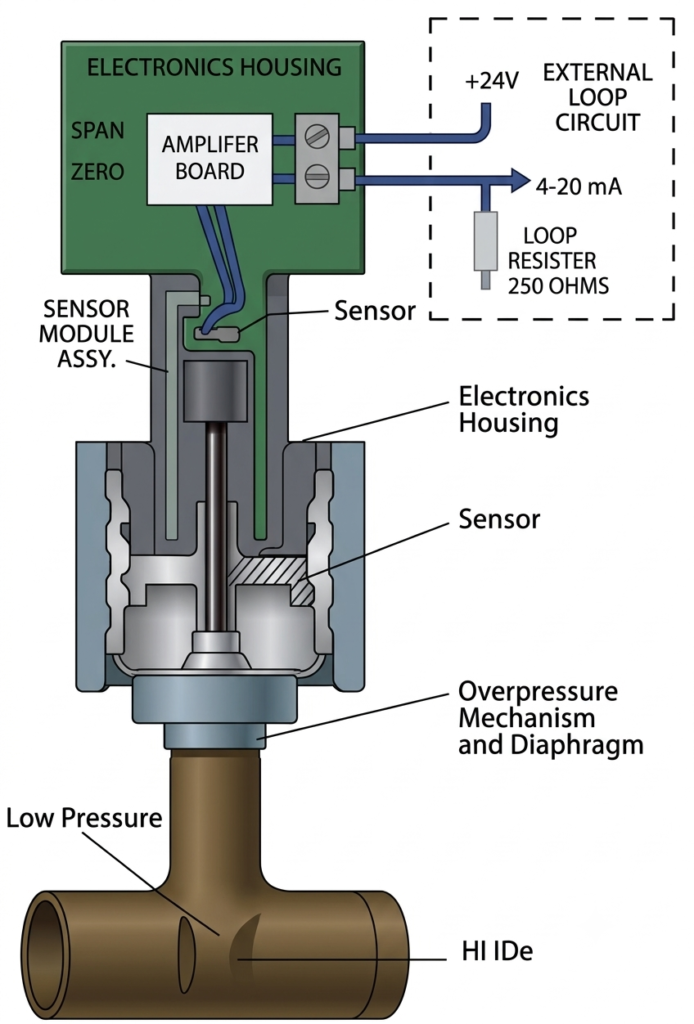
A DP transmitter consists of a pressure-sensing assembly, isolation components, electronic circuitry, and process connections.
The principal components are explained below.
1. Isolation Diaphragms
Isolation diaphragms separate the process fluid from the internal sensing mechanism. They transmit pressure through a compatible fill fluid in many conventional designs.
These diaphragms help protect sensitive components from direct contact with the process medium.
2. Measuring Cell
The measuring cell detects the difference between the pressures applied to the two sides. It contains the sensing elements and associated mechanical or electrical structures.
Its design determines the measurement range, sensitivity, and performance characteristics of the transmitter.
3. Sensor Element
The sensor converts the pressure-induced mechanical response into a measurable signal. Depending on the design, it may use capacitive, piezoresistive, strain-gauge, or resonant technology.
4. Signal Conditioning Circuit
The signal conditioning circuit amplifies and processes the sensor output. It may also apply linearization, temperature compensation, and other corrections.
5. Output Electronics
The output electronics generate the required analog or digital communication signal. Smart transmitters may also provide diagnostic information and configuration options.
6. High- and Low-Pressure Connections
The HP and LP connections link the transmitter to the process through impulse lines, manifolds, or suitable direct-mount arrangements.
7. Housing
The housing protects the sensor electronics from environmental conditions. Its material, ingress protection, and hazardous-area certification must be appropriate for the installation.
Types of Differential Pressure Transmitters
Differential pressure transmitters can be classified according to their sensing technology. The most common types are described below.
1. Capacitive Differential Pressure Transmitter
A capacitive DP transmitter detects pressure-induced changes in capacitance.
A sensing diaphragm is positioned between electrodes. When differential pressure changes, the diaphragm moves, altering the capacitance between the sensing structures. The electronics convert this change into a pressure measurement.
Advantages:
- High measurement sensitivity
- Good accuracy in suitable applications
- Low mechanical displacement
- Availability in a wide range of industrial designs
Applications: Flow measurement, tank-level measurement, filter monitoring, and general process instrumentation.
2. Piezoresistive Differential Pressure Transmitter
A piezoresistive differential pressure transmitter uses a sensing element whose electrical resistance changes when mechanical stress is applied.
The pressure difference produces stress in the sensing structure. The resulting resistance change is measured by an electronic circuit and converted into an output signal.
Advantages:
- Compact sensor design
- Good sensitivity
- Suitable for many industrial pressure ranges
- Compatibility with electronic signal processing
Applications: Industrial process measurement, hydraulic systems, and compact pressure-monitoring equipment.
3. Strain-Gauge Differential Pressure Transmitter
A strain-gauge differential pressure transmitter measures deformation using strain-sensitive electrical elements attached to or integrated with a sensing structure.
As the pressure difference changes, the structure deforms slightly. This deformation changes the resistance of the strain gauges, producing a measurable electrical response.
Advantages:
- Established measurement technology
- Suitable for a variety of pressure ranges
- Compatible with bridge-based measurement circuits
Applications: Industrial pressure monitoring, test equipment, and specialized process measurement systems.
4. Inductive Differential Pressure Transmitter
An inductive transmitter uses a change in inductance associated with the movement of a magnetic or ferromagnetic component.
The pressure difference produces movement in the sensing mechanism, which changes the electrical characteristics of the inductive circuit. The electronics interpret this change as a pressure measurement.
Applications: Selected industrial measurement systems where inductive sensing is suitable for the required operating conditions.
5. Resonant-Wire Differential Pressure Transmitter
A resonant-wire transmitter uses the change in the resonant frequency of a wire or similar vibrating element under mechanical stress.
When differential pressure changes, the stress in the sensing mechanism changes. This affects the resonant frequency, which is measured electronically and converted into a pressure value.
Advantages:
- Frequency-based measurement
- Potentially good long-term stability in suitable designs
- Digital processing capabilities in compatible instruments
6. MEMS-Based Differential Pressure Transmitter
Microelectromechanical systems (MEMS) use miniature mechanical structures integrated with electronic sensing elements.
These sensors can measure pressure-induced movement or stress on a microscopic scale. The exact sensing method depends on the design.
Applications: Compact industrial instruments, equipment monitoring, and applications requiring miniature sensing technology.
7. Optical Differential Pressure Sensor
An optical pressure sensor detects pressure-induced changes using light, optical interference, or fiber-optic measurement techniques.
Optical sensing can be useful in specialized applications where electrical isolation or resistance to electromagnetic interference is important. However, suitability depends on the particular sensor and installation requirements.
Comparison of Differential Pressure Transmitter Types
| Sensor type | Measurement principle | Main characteristic |
| Capacitive | Change in capacitance | High sensitivity |
| Piezoresistive | Change in electrical resistance under stress | Compact sensing element |
| Strain gauge | Resistance change caused by deformation | Established industrial technology |
| Inductive | Change in inductance | Uses magnetic or inductive sensing |
| Resonant wire | Change in resonant frequency | Frequency-based measurement |
| MEMS | Microscopic mechanical sensing | Compact construction |
| Optical | Pressure-related optical change | Useful in selected specialized environments |
The best choice depends on accuracy requirements, operating pressure, temperature, process-fluid compatibility, environmental conditions, and maintenance needs.
Differential Pressure Transmitter Output Signal
The transmitter converts the measured pressure difference into a signal that can be transmitted to a control system.
1. 4–20 mA Analog Output
The 4–20 mA signal is widely used in industrial instrumentation. Four milliamperes represent the configured lower range value, while 20 milliamperes represent the configured upper range value under normal linear operation.
For example, consider a transmitter calibrated for a differential pressure range of 0–10 bar.
- 0 bar DP corresponds to 4 mA.
- 5 bar DP corresponds to 12 mA.
- 10 bar DP corresponds to 20 mA.
The output current can be calculated using:
Where:
- = Output current in mA
- = Measured differential pressure
- = Lower range value
- = Upper range value
For a 0–10 bar range and a measured DP of 5 bar:
This relationship assumes a linear output configuration and a measurement within the calibrated range.
2. HART Communication
HART combines a conventional 4–20 mA analog signal with digital communication over the same wiring.
It allows technicians to access additional device information, configure the transmitter, check diagnostics, and perform supported maintenance functions using compatible equipment.
3. Foundation Fieldbus
Foundation Fieldbus provides digital communication for compatible process instruments. Depending on the system design, instruments can exchange process data, diagnostic information, and configuration details over a fieldbus network.
4. PROFIBUS PA
PROFIBUS PA is a digital communication technology designed for process automation. It supports communication between compatible field instruments and control systems.
The selected protocol must match the plant’s control-system architecture and instrument requirements.
Applications of Differential Pressure Transmitters
Differential pressure transmitters are used for several important measurements in industrial plants.
1. Flow Measurement
A DP transmitter measures the pressure difference created when fluid passes through a primary flow element, such as an orifice plate, Venturi tube, or flow nozzle.
For many conventional differential-pressure flow installations, the relationship is approximately:
Where:
- = Volumetric flow rate
- = Differential pressure
This means that flow is generally proportional to the square root of differential pressure, rather than directly proportional to it.
For example, if the differential pressure across an orifice plate increases fourfold, the flow rate approximately doubles, assuming the same installation conditions and a valid square-root relationship.
The control system or transmitter must apply the appropriate square-root extraction when a flow-rate output is required. The exact calculation also depends on the primary element, fluid properties, and installation.
Industrial applications include:
- Boiler feedwater flow
- Steam flow measurement
- Compressed-air flow
- Fuel-gas flow
- Process-water flow
- Airflow in ducts and ventilation systems
2. Liquid-Level Measurement in Open Tanks
A DP transmitter can measure liquid level in an open tank by detecting the hydrostatic pressure produced by the liquid column.
The pressure at the bottom of the tank is approximately:
Where:
- = Hydrostatic pressure
- = Liquid density
- = Gravitational acceleration
- = Liquid height
In a typical open-tank installation, the high-pressure connection is connected to the bottom of the tank, while the low-pressure connection is referenced to atmospheric pressure.
The measured pressure difference corresponds to the liquid head. If the liquid density is known and remains sufficiently stable, the transmitter can be calibrated to indicate liquid level.
3. Liquid-Level Measurement in Closed Tanks
In a closed tank, pressure above the liquid can vary due to vapor pressure or gas blanketing. This pressure can affect a simple bottom-pressure measurement.
A DP transmitter can compensate for the pressure above the liquid by connecting the HP side to the bottom of the vessel and the LP side to the appropriate upper-vessel pressure reference.
For a conventional arrangement, the differential pressure represents the hydrostatic head when the pressure connections and calibration are configured correctly.
For pressurized tanks, installation details such as wet legs, dry legs, elevation, and fill-fluid effects must be considered.
4. Filter and Strainer Monitoring
A DP transmitter measures the pressure difference between the inlet and outlet of a filter or strainer.
As contaminants accumulate, the pressure drop may increase. The control system can use this measurement to trigger an alarm or maintenance request when a defined limit is reached.
This helps prevent excessive pressure loss and supports condition-based maintenance.
5. Pressure Drop Across Heat Exchangers
A DP transmitter can monitor the pressure difference across a heat exchanger or similar equipment.
An abnormal change may indicate fouling, blockage, changes in flow, or another process issue. The measurement should be interpreted alongside flow rate and operating conditions because pressure drop is not determined by fouling alone.
6. Airflow Monitoring in Cement Plants
In cement manufacturing, differential pressure measurement is important for monitoring gas flow and equipment condition.
Typical applications include:
- Bag-filter pressure drop
- Airflow measurement across suitable primary elements
- Fan and duct monitoring
- Pressure differences across selected process equipment
- Draft monitoring in compatible arrangements
For a bag filter, an increasing differential pressure may indicate dust accumulation or cleaning-system problems. A sudden decrease may indicate a damaged filter bag, bypass leakage, or a change in operating conditions.
The actual diagnosis should be confirmed using other process indicators.
7. Boiler and Power-Plant Applications
DP transmitters are used in power plants for steam and water flow measurement, air-flow monitoring, filter condition monitoring, and selected level-measurement applications.
They may form part of control and protection systems, subject to the design requirements of the specific application.
For critical services, instrument selection, installation, testing, and maintenance must comply with the applicable plant standards and safety requirements.
Difference Between Differential, Gauge, and Absolute Pressure
These three pressure measurements have different reference points.
| Parameter | Differential pressure | Gauge pressure | Absolute pressure |
| Measurement reference | A second pressure point | Local atmospheric pressure | Perfect vacuum |
| Basic meaning | Difference between two pressures | Pressure above or below atmosphere | Total pressure relative to vacuum |
| Typical application | Flow, level, filter monitoring | Pipeline and vessel pressure | Vacuum and thermodynamic measurements |
| Basic relationship | P1 − P2 | Pabs − Patm | Pgauge + Patm |
A differential pressure transmitter is appropriate when the difference between two pressure points is the required process variable. Gauge or absolute pressure instruments are more appropriate when the application requires one of those specific pressure references.
Some instrument designs can measure more than one pressure variable, but this depends on the model.
DP Transmitter Manifold and Its Functions
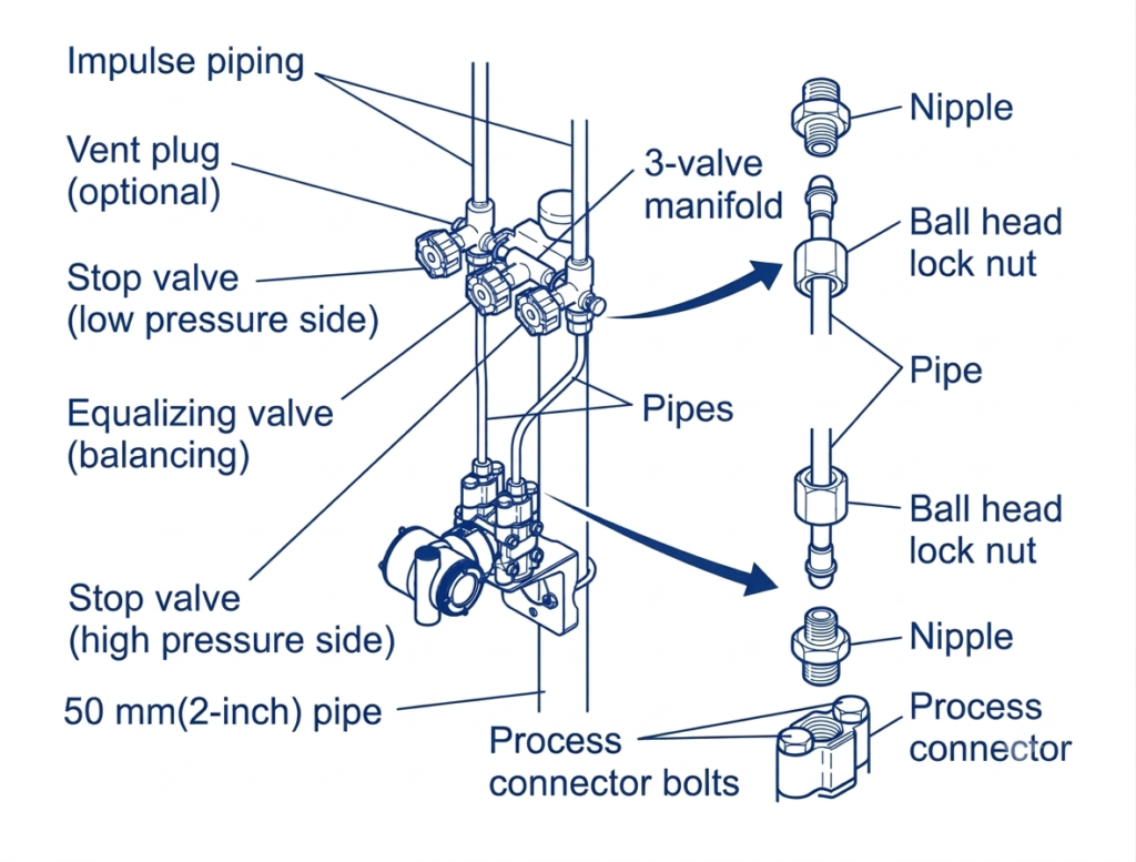
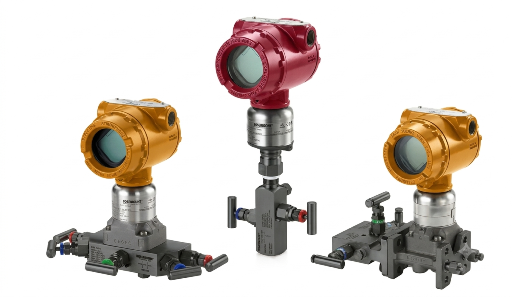
A manifold is a valve assembly installed between the process connections and a differential pressure transmitter. It enables the instrument to be isolated, equalized, and, where provided, vented or drained for approved maintenance and calibration procedures.
1. Three-Valve Manifold
A three-valve manifold normally contains:
- One HP block valve
- One LP block valve
- One equalizing valve
The block valves isolate the transmitter from the process. The equalizing valve connects the high- and low-pressure sides to bring their pressures closer together when operated under the correct procedure.
This arrangement is common in conventional DP transmitter installations.
2. Five-Valve Manifold
A five-valve manifold generally includes two block valves, one equalizing valve, and two additional vent or drain valves.
The additional valves provide facilities for selected testing and maintenance tasks. Their use depends on the manifold design, process fluid, and approved operating procedure.
3. Two-Valve Manifold
A two-valve arrangement may be used in selected pressure-instrument installations, but it is not a universal substitute for the manifold required by a DP measurement application.
Always verify the actual valve configuration against the instrument installation design.
Important Manifold Safety Precautions
- Follow the manufacturer’s operating sequence and plant procedures.
- Confirm that the process fluid and pressure conditions permit the planned work.
- Do not open a vent or drain unless its discharge can be handled safely.
- Avoid exposing the sensor to an excessive differential pressure.
- Verify the correct valve positions before returning the transmitter to service.
Incorrect manifold operation can cause measurement errors or damage to the sensing element.
Installation of a Differential Pressure Transmitter
Correct installation is essential for reliable measurement. The required arrangement depends on whether the transmitter measures liquid, gas, steam, flow, or level.
1. Identify the HP and LP Connections
Connect the high-pressure port to the higher-pressure process connection and the low-pressure port to the lower-pressure connection.
Incorrect connections can cause a negative or otherwise misleading measurement.
2. Install Suitable Impulse Lines
Impulse lines carry process pressure to the transmitter. They must be correctly sized, routed, supported, and protected against blockage, leakage, freezing, and other relevant process hazards.
The routing depends on the fluid and application.
3. Consider Transmitter Elevation
The vertical position of the transmitter relative to the process taps can introduce hydrostatic pressure effects in the connecting lines.
These effects are particularly important in liquid-level applications and installations using wet legs. Apply the correct zero and range adjustments for the actual arrangement.
4. Remove Trapped Gas or Liquid Where Required
Trapped gas in liquid-service lines or accumulated liquid in gas-service lines can affect measurement accuracy.
The impulse-line arrangement and venting or draining procedure should follow the application design and manufacturer instructions.
5. Check Process Compatibility
Confirm that wetted materials, isolation diaphragms, seals, and fill fluids are compatible with the process medium and operating temperature.
6. Verify Electrical Connections
Check the power supply, loop wiring, polarity, grounding, shielding, and communication requirements against the transmitter manual and control-system design.
7. Configure the Range and Units
Set the correct lower and upper range values, engineering units, damping, output configuration, and any required square-root extraction.
For flow measurement, confirm whether square-root extraction is performed in the transmitter or in the receiving control system. Avoid applying it twice.
How to Calibrate a Differential Pressure Transmitter
Calibration verifies whether the transmitter produces the expected output for known applied differential pressures.
A suitable pressure calibrator, reference instrument, or calibration system is required. The test equipment must have appropriate accuracy and a range suitable for the transmitter.
Step 1: Review the Calibration Range
Check the instrument’s configured lower range value and upper range value.
For example, a transmitter may be calibrated from 0 to 100 kPa differential pressure.
Step 2: Follow the Approved Isolation Procedure
Place the process in the required safe condition and isolate the instrument according to the approved plant procedure.
Use the manifold and pressure connections as specified by the manufacturer. Never assume that closing a valve alone makes a pressurized instrument safe to open.
Step 3: Connect the Calibration Equipment
Connect the pressure source to the appropriate high- and low-pressure sides. Ensure that the test setup can safely apply the required differential pressure.
For differential calibration, control the pressure on both sides as necessary. Applying the same pressure to both sides produces approximately zero differential pressure, provided the pressures are properly balanced.
Step 4: Apply Known Pressure Values
Apply test points across the configured range, such as 0%, 25%, 50%, 75%, and 100%.
For a 0–100 kPa range, the corresponding test values are:
| Percentage of range | Applied differential pressure |
| 0% | 0 kPa |
| 25% | 25 kPa |
| 50% | 50 kPa |
| 75% | 75 kPa |
| 100% | 100 kPa |
Step 5: Check the Output Signal
For a linear 4–20 mA output configured from 0 to 100 kPa, the expected values are:
| Differential pressure | Expected output |
| 0 kPa | 4 mA |
| 25 kPa | 8 mA |
| 50 kPa | 12 mA |
| 75 kPa | 16 mA |
| 100 kPa | 20 mA |
Compare the measured output with the expected value and the manufacturer’s specified tolerance.
Step 6: Adjust Zero or Span if Necessary
If the transmitter fails the acceptance criteria, investigate the test setup and configuration before making adjustments. Apply zero or span trimming only when required and permitted by the maintenance procedure.
Step 7: Verify the Calibration
Repeat the test points after adjustment. Check the increasing and decreasing pressure directions where required to identify hysteresis or repeatability problems.
Record the as-found and as-left results, equipment identification, reference equipment, and final configuration.
Step 8: Restore the Instrument to Service
Reconnect and pressurize the instrument using the approved sequence. Confirm that the manifold valves are in their required operating positions and check for leaks or abnormal readings.
Safety note: Calibration on a live process can be hazardous. The procedure must account for stored pressure, process-fluid exposure, isolation requirements, and the consequences of taking the measurement out of service.
Common Differential Pressure Transmitter Problems and Troubleshooting
Incorrect readings do not always indicate a faulty transmitter. The problem may originate in the impulse lines, manifold, wiring, configuration, or process itself.
| Problem | Possible cause | Recommended checks |
| No output signal | Loss of supply, wiring fault, or failed electronics | Verify the power supply, loop wiring, and instrument status |
| Output remains at zero | Incorrect range, blocked lines, or pressure not reaching the sensor | Check the configuration and impulse-line condition |
| Negative reading | HP and LP connections reversed or actual reverse differential pressure | Verify process connections and the expected pressure relationship |
| Unstable output | Process fluctuations, vibration, gas or liquid pockets, or electrical interference | Check process stability, line routing, grounding, and damping |
| Zero shift | Unequal pressure effects, mounting or temperature effects, or sensor drift | Verify equal-pressure response and installation conditions |
| Incorrect flow indication | Wrong range, incorrect square-root extraction, or unsuitable primary-element configuration | Check flow configuration and the transmitter/control-system setup |
| Slow response | Restricted impulse lines or excessive damping | Inspect the lines and review damping settings |
| Excessive filter DP | Filter loading, blocked passages, or changed operating conditions | Compare inlet/outlet pressure with flow and maintenance history |
| Manifold leakage | Damaged seals, loose fittings, or valve damage | Follow the isolation procedure and inspect the assembly safely |
Before replacing a transmitter, verify the applied pressure, the valve positions, the configured range, and the integrity of the signal loop.
Factors to Consider When Selecting a DP Transmitter
The correct transmitter should be selected according to the actual process requirements rather than differential pressure range alone.
Consider the following factors:
- Differential pressure range: Select a calibrated range that covers the expected operating conditions and required measurement resolution.
- Static pressure rating: Confirm that the transmitter can withstand the maximum pressure applied to both sides, even when the differential pressure is small.
- Overpressure protection: Check the specified limits for differential and common-mode pressure.
- Accuracy and stability: Select performance appropriate to the process and control requirements.
- Process temperature: Confirm the allowable process and ambient temperature ranges.
- Wetted materials: Choose materials compatible with the process fluid and cleaning requirements.
- Output and communication: Check compatibility with the PLC, DCS, indicator, or other receiving system.
- Environmental protection: Verify enclosure protection, hazardous-area approvals, and other relevant certifications.
- Installation arrangement: Account for impulse lines, manifolds, mounting orientation, elevation, and accessibility.
- Maintenance requirements: Consider diagnostics, calibration access, spare-parts availability, and lifecycle costs.
Always consult the manufacturer’s datasheet and installation manual for model-specific limits.
Conclusion
A differential pressure transmitter is an important instrument for measuring pressure differences in industrial process systems. Its measurements support flow calculation, tank-level monitoring, filter-condition assessment, and pressure-drop analysis across process equipment.
Understanding the working principle, sensor technology, output signal, installation arrangement, and calibration procedure helps engineers and technicians obtain reliable measurements and troubleshoot problems efficiently.
For dependable operation, select a transmitter that matches the process conditions, verify the HP and LP connections, install the impulse lines correctly, configure the measurement range carefully, and follow the manufacturer’s instructions for calibration and maintenance.
Read Next: