A piezoresistive differential pressure transmitter measures the pressure difference between two points and converts it into an electrical signal for monitoring and process control. It uses the piezoresistive effect, in which the electrical resistance of a material changes when mechanical stress is applied. Silicon is commonly used as the sensing material because of its high sensitivity to pressure-induced strain.
These transmitters are widely used in industrial automation, HVAC systems, hydraulic equipment, water treatment plants, and process industries. Their high sensitivity, compact construction, and reliable measurement performance make them suitable for detecting small pressure differences.
What Is a Piezoresistive Differential Pressure Transmitter?
A piezoresistive differential pressure transmitter is an instrument that measures the difference between two applied pressures, usually identified as high-pressure (HP) and low-pressure (LP) inputs.
The transmitter directs these pressures to opposite sides of a sensing arrangement. The resulting pressure difference produces mechanical stress in a diaphragm or silicon sensing element. Piezoresistive elements detect this stress by changing their electrical resistance.
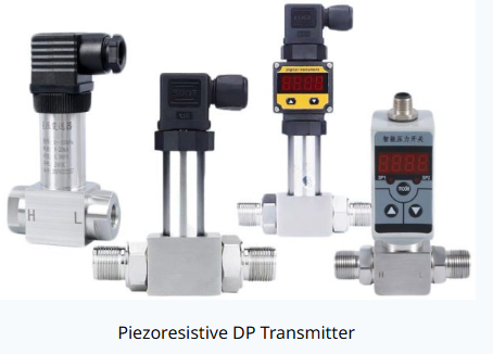
The transmitter’s electronic circuit converts these resistance changes into a calibrated output signal proportional to the measured differential pressure.
The differential pressure is expressed as:
Where:
- = Differential pressure
- = Pressure at the high-pressure port
- = Pressure at the low-pressure port
For example, if the high-pressure port receives 250 kPa and the low-pressure port receives 200 kPa, the differential pressure is:
The transmitter measures a differential pressure of 50 kPa.
Working Principle of a Piezoresistive Differential Pressure Transmitter
The working principle of a piezoresistive differential pressure transmitter is based on the relationship between mechanical stress and electrical resistance. When a pressure difference acts on the sensing diaphragm, the diaphragm deforms and transfers stress to the piezoresistive elements.
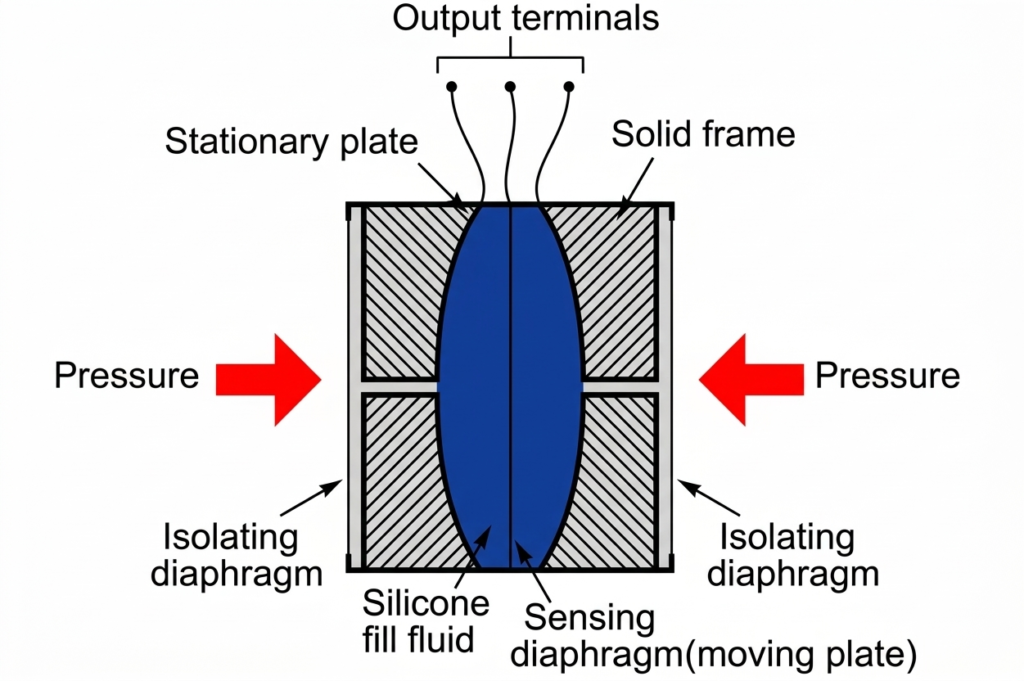
The operating process involves the following steps.
- Pressure application: The high-pressure and low-pressure connections receive pressures from two measurement points.
- Diaphragm deformation: The difference between the applied pressures creates a force that causes the sensing diaphragm to deflect.
- Resistance variation: The mechanical stress changes the resistance of the piezoresistive elements fabricated on or integrated with the silicon sensing structure.
- Bridge circuit operation: The piezoresistors are commonly connected in a Wheatstone bridge. Resistance changes unbalance the bridge and generate a small differential voltage.
- Signal conditioning: Electronic circuitry amplifies the bridge output and applies calibration, linearization, and temperature compensation as required.
- Signal transmission: The conditioned output is supplied to a PLC, DCS, controller, display, or monitoring system.
Within its specified operating range, the output signal corresponds to the applied differential pressure.
What Is the Piezoresistive Effect?
The piezoresistive effect is the change in electrical resistivity of a material when mechanical stress or strain is applied. It differs from the piezoelectric effect, which produces an electrical charge in response to mechanical stress.
Silicon is particularly useful for piezoresistive pressure measurement because its electrical resistance can change significantly under mechanical stress. This enables a piezoresistive pressure sensor to detect small pressure variations with high sensitivity.
The resistance of a sensing element can be expressed as:
Where:
- = Electrical resistance
- = Electrical resistivity
- = Length of the conducting path
- = Cross-sectional area
When stress is applied, both the dimensions and the resistivity of the sensing material can change. In silicon, the change in resistivity is an important contributor to the piezoresistive response.
For small changes, the resistance variation is commonly described by:
Where:
- = Change in resistance
- = Initial resistance
- = Gauge actor
- = Mechanical strain
This relationship is a simplified representation of the piezoresistive response. The actual performance depends on the sensing material, crystal orientation, element geometry, and stress distribution.
Piezoresistive Pressure Sensor Diagram
A typical piezoresistive pressure sensor contains a pressure-sensitive diaphragm, piezoresistive elements, a Wheatstone bridge, and signal-conditioning electronics.
The basic measurement sequence can be represented as follows:
Applied pressure → Diaphragm deformation → Resistance change → Wheatstone bridge output → Signal conditioning → Electrical output
In a differential pressure transmitter, the HP and LP ports provide the two pressure inputs. The sensor responds to their difference rather than measuring only one pressure relative to atmospheric pressure.
A simplified block diagram is:
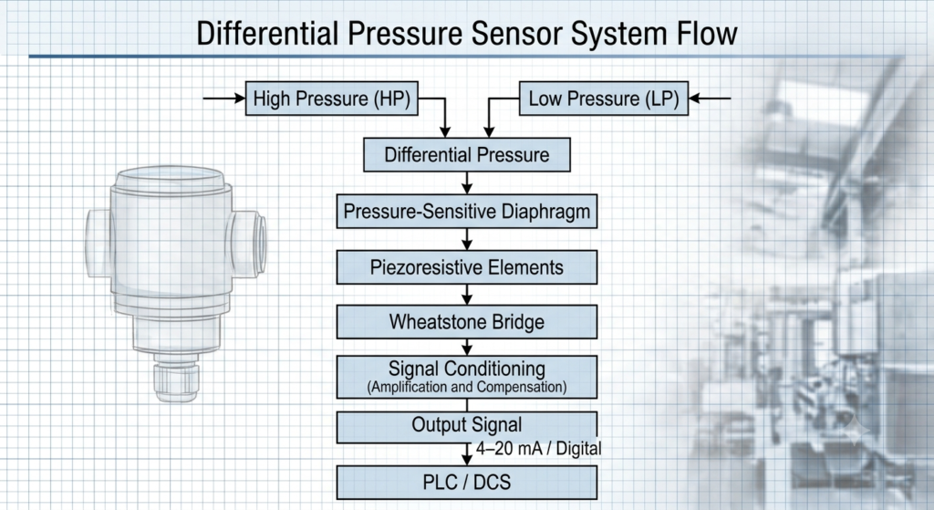
This is a functional block diagram, not a detailed internal construction drawing. Actual sensor arrangements vary by manufacturer and design.
Main Components of a Piezoresistive Differential Pressure (Dp) Transmitter
A typical transmitter combines mechanical pressure isolation, a sensitive element, and electronic signal processing.
1. Silicon Sensing Element
The silicon sensing element detects the mechanical stress produced by the applied differential pressure. Piezoresistors are formed in selected regions of the silicon structure to provide a measurable change in resistance.
The arrangement of these elements determines the sensor’s sensitivity, linearity, and response to pressure.
2. Sensing Diaphragm
The diaphragm is the pressure-responsive part of the sensor. It deflects when the pressure on one side differs from the pressure on the other side.
Depending on the design, the sensing diaphragm may be made from silicon or incorporated into a metal-isolated assembly. Industrial transmitters often use corrosion-resistant metal isolation diaphragms to protect the internal sensing element from the process fluid.
3. Pressure Ports
The high-pressure and low-pressure ports connect the transmitter to the two process measurement points. Correct connection of these ports is essential for obtaining the intended differential pressure reading.
Reversing the connections can reverse the sign of the measured differential pressure in instruments configured for bidirectional measurement.
4. Fill Fluid and Isolation Diaphragms
Some industrial designs use isolation diaphragms and an incompressible fill fluid, commonly silicone oil, to transfer process pressure to the internal sensing element.
The fill fluid transmits pressure while keeping the process medium away from sensitive semiconductor components. Other sensor designs use different pressure-transfer arrangements.
5. Wheatstone Bridge Circuit
The piezoresistors are frequently arranged in a Wheatstone bridge. When pressure changes their resistance, the bridge becomes unbalanced and produces a small voltage proportional to the applied stress over the intended measurement range.
The bridge arrangement helps convert minute resistance changes into a usable electrical measurement.
6. Signal-Conditioning Electronics
The electronic circuit amplifies the sensor output and compensates for factors such as temperature variation and sensor nonlinearity. Depending on the model, it may also provide diagnostics, configuration, digital communication, and output scaling.
7. Housing and Electrical Connections
The enclosure protects the sensing assembly and electronics from environmental conditions. Industrial models may include ingress protection, electromagnetic compatibility features, and materials selected for corrosive or demanding environments.
The appropriate enclosure rating and material selection depend on the installation conditions.
Output Signals of a Piezoresistive Pressure Transmitter
After the sensing element detects the pressure difference, the electronics convert the measurement into an output suitable for control and monitoring.
Common output options include:
- 4–20 mA: Widely used in industrial process control and PLC or DCS systems.
- Voltage output: Certain models provide outputs such as 0–5 V or 1–5 V, depending on their specifications.
- HART communication: Available in compatible industrial transmitters for configuration, diagnostics, and digital communication over a current loop.
- RS-485 and Modbus: Supported by selected models for digital communication.
- Other digital interfaces: CANopen and other protocols may be available in application-specific devices.
Not every piezoresistive transmitter supports all these outputs. The available signal type and communication protocol must be verified from the manufacturer’s datasheet.
Advantages of Piezoresistive Differential Pressure Transmitters
Piezoresistive differential pressure transmitters offer several advantages in measurement and control applications.
High Sensitivity
Silicon piezoresistors can detect small stress-induced resistance changes, making them suitable for applications that require sensitive differential pressure measurement.
Good Accuracy and Repeatability
Properly designed and calibrated transmitters provide consistent measurements over their specified operating range. Actual accuracy depends on the sensor design, temperature effects, calibration, and installation conditions.
Compact Construction
Microfabricated silicon sensing elements allow manufacturers to develop compact sensors for industrial instruments, laboratory equipment, and embedded systems.
Fast Response
Piezoresistive sensors can respond quickly to pressure changes. The actual response time and usable dynamic bandwidth depend on the sensor, pressure connection, damping, and signal-conditioning electronics.
Multiple Output Options
Depending on the model, the transmitter can provide analog or digital signals for integration into process automation and data acquisition systems.
Compatibility with Different Process Conditions
Suitable isolation diaphragms, wetted materials, seals, and pressure connections allow some models to operate with corrosive or demanding process media. Material compatibility must always be checked before installation.
Limitations of Piezoresistive Differential Pressure Transmitters
Despite their advantages, these instruments have certain limitations.
- Temperature sensitivity: Changes in temperature can affect the resistance of the sensing elements and may introduce measurement errors if compensation is inadequate.
- Overpressure risk: Pressure exceeding the specified limits can damage the diaphragm or sensing element.
- Process compatibility: The selected wetted materials and seals must withstand the process fluid and operating conditions.
- Calibration requirements: Periodic calibration may be necessary to maintain measurement accuracy.
- Installation effects: Incorrect impulse-line routing, trapped gas, liquid accumulation, vibration, or improper port connections can affect readings.
Selecting the correct pressure range and installing the transmitter according to the manufacturer’s instructions helps minimize these problems.
Applications of Piezoresistive Differential Pressure Transmitters
Piezoresistive differential pressure transmitters are used wherever the difference between two pressures provides important information about system performance.
1. Flow Measurement
Differential pressure transmitters measure the pressure drop across primary flow elements such as orifice plates, venturi tubes, and other differential-pressure flow devices. With the appropriate configuration and flow calculation, the differential pressure can be used to determine fluid flow rate.
For many common differential-pressure flow arrangements, flow rate is approximately proportional to the square root of differential pressure, subject to the applicable calibration and operating conditions.
2. Filter Monitoring
The transmitter measures the pressure difference across a filter. As the filter becomes clogged, its pressure drop generally increases at a comparable flow rate. This information helps operators identify when cleaning or replacement may be required.
3. HVAC Systems
In heating, ventilation, and air-conditioning systems, differential pressure measurement can be used to monitor air filters, duct pressure, ventilation systems, and building pressurization.
4. Liquid Level Measurement
A differential pressure transmitter can measure liquid level in a tank by detecting the hydrostatic pressure associated with the liquid column. The measurement setup must account for tank pressure, liquid density, mounting elevation, and any wet-leg or remote-seal arrangement.
5. Hydraulic and Pneumatic Systems
These transmitters monitor pressure differences across components such as valves, filters, actuators, and hydraulic circuits. They help assess operating conditions and identify abnormal pressure losses.
6. Chemical and Process Industries
Chemical plants and other process facilities use differential pressure instruments for flow monitoring, filter condition assessment, vessel measurements, and pressure-drop monitoring. The selected transmitter must be compatible with the process fluid and required safety classification.
7. Water and Wastewater Treatment
Applications include filter-bed monitoring, pressure-drop measurement, pumping systems, and selected flow measurement installations.
8. Laboratory and OEM Equipment
Compact piezoresistive pressure sensors are used in test benches, calibration systems, medical or analytical equipment, and original equipment manufacturer (OEM) products where size and sensitivity are important.
Piezoresistive Pressure Sensor vs. Other Pressure-Sensing Technologies
Piezoresistive sensing is one of several technologies used to measure pressure. The best choice depends on the measurement range, required response, operating temperature, process compatibility, and output requirements.
| Feature | Piezoresistive sensor | Capacitive sensor | Piezoelectric sensor |
| Measurement principle | Stress-induced resistance change | Pressure-induced capacitance change | Stress-induced electrical charge |
| Static pressure measurement | Suitable | Suitable | Generally unsuitable for sustained static pressure |
| Dynamic response | Can be fast | Depends on design | Often well suited to dynamic pressure |
| Typical sensing material | Silicon or other resistive materials | Conductive plates and dielectric structure | Piezoelectric materials |
| Common applications | Pressure and differential pressure measurement | Low-pressure and process measurements | Pulsating pressure and transient measurements |
The performance of each technology varies by design. A piezoresistive sensor is often a suitable choice when both static and changing pressure must be measured using a compact electrical sensing element.
How to Select a Piezoresistive Differential Pressure Transmitter
Before selecting a transmitter, consider the following parameters:
- Differential pressure range: Select a calibrated range that covers normal operation while providing adequate resolution.
- Static line pressure: Check the maximum pressure that may be present at the HP and LP ports, even when the differential pressure is small.
- Overpressure capability: Verify the allowable pressure on each port and the permitted differential overpressure.
- Accuracy: Review reference accuracy, temperature effects, long-term stability, and total measurement uncertainty.
- Process media: Choose compatible diaphragm, seal, and wetted materials.
- Output and communication: Confirm whether the system requires 4–20 mA, voltage, HART, Modbus, or another interface.
- Environmental protection: Consider ambient temperature, humidity, vibration, enclosure rating, and hazardous-area requirements.
- Installation requirements: Check mounting orientation, impulse lines, manifold arrangements, and calibration accessibility.
Correct selection helps improve measurement reliability, reduce maintenance, and support safe process operation.
Conclusion
A piezoresistive differential pressure transmitter measures the pressure difference between two points by using stress-induced resistance changes in a sensing element. The piezoresistive effect enables the instrument to detect diaphragm deformation and convert it into an electrical signal through a bridge circuit and signal-conditioning electronics.
Its sensitivity, compact design, and ability to measure static as well as changing pressure make it useful in flow measurement, filter monitoring, HVAC systems, hydraulic equipment, and industrial process control. Understanding the working principle, sensor construction, output signals, limitations, and selection criteria helps engineers choose and apply the correct transmitter for reliable differential pressure measurement.
Read Next:
- Transmitter: Types, Working Principle, and Examples
- SMART Transmitter: Working Principle, Components, Advantages
- Level Transmitter Calibration Procedure
- Level Transmitter: Types, Working Principle & Applications
- Differential Pressure Transmitter: Working Principle, Types
- Capacitance Differential Pressure Transmitter: Working Principle, Construction
- Strain-Gauge Differential Pressure Transmitter: Working Principle, Diagram, Components, and Applications