Bonded and unbonded strain gauges are two types of resistance strain sensors used to measure mechanical deformation in industrial instrumentation, pressure transducers, force measurement systems, and other engineering applications. Both operate by detecting changes in electrical resistance, but they differ in construction, the method used to produce strain, and their installation requirements.
A bonded strain gauge has a sensing element attached directly to the surface of a component or elastic sensing member. An unbonded strain gauge uses fine resistance wires stretched between fixed and movable supports, allowing the wires to experience changes in tension when the movable support shifts.
Understanding the difference between bonded and unbonded strain gauges helps engineers select the appropriate sensing technology for pressure measurement, load cells, displacement measurement, and industrial control systems.
In this article, we will examine their construction, working principles, advantages, limitations, applications, and key differences.
What Is a Strain Gauge?
A strain gauge is a transducer that measures the deformation of a material subjected to an external force. In a resistance strain gauge, the deformation produces a change in electrical resistance that can be measured using an electrical circuit.
When a metallic conductor is stretched, its length increases and its cross-sectional area generally decreases. These changes usually increase its electrical resistance. Compression generally produces the opposite geometrical changes.
The resistance of a conductor is expressed as:
Where:
- = electrical resistance in ohms
- = electrical resistivity of the material
- = length of the conductor
- = cross-sectional area of the conductor
The relationship between resistance change and strain is expressed using the gauge factor:
Where:
- = gauge factor
- = change in resistance
- = initial resistance
- = mechanical strain
The small resistance variation is commonly measured using a Wheatstone bridge. Signal-conditioning electronics then convert the bridge output into a usable measurement.
Depending on the sensor design and calibration, this measurement can be used to determine strain or to measure a related quantity such as pressure, force, or load.
What Is a Bonded Strain Gauge?
A bonded strain gauge is a resistance sensor whose sensing element is firmly attached to the surface of a component using a suitable adhesive or bonding process.
The sensing element is commonly made from a thin metallic foil or fine resistance wire mounted on an insulating backing. When the component deforms, the bonded gauge follows the surface deformation and experiences a corresponding change in resistance.
Bonded strain gauges are widely used in pressure transducers, load cells, torque sensors, and experimental stress analysis.
Construction of a bonded strain gauge
A typical bonded strain gauge consists of the following parts:
- Sensing element: A metallic foil grid or resistance wire that changes resistance during deformation.
- Insulating backing: Electrically isolates the sensing element from the test component.
- Adhesive layer: Transfers the component’s surface strain to the sensing element.
- Electrical terminals and leads: Connect the gauge to the measuring circuit.
- Protective coating: May be applied to protect the gauge against moisture, contamination, and mechanical damage.
The gauge is bonded to a prepared surface so that the strain transfer is reliable. In a pressure transducer, the gauge is commonly installed on a diaphragm or another elastic sensing element that deforms under pressure.
Working principle of a bonded strain gauge
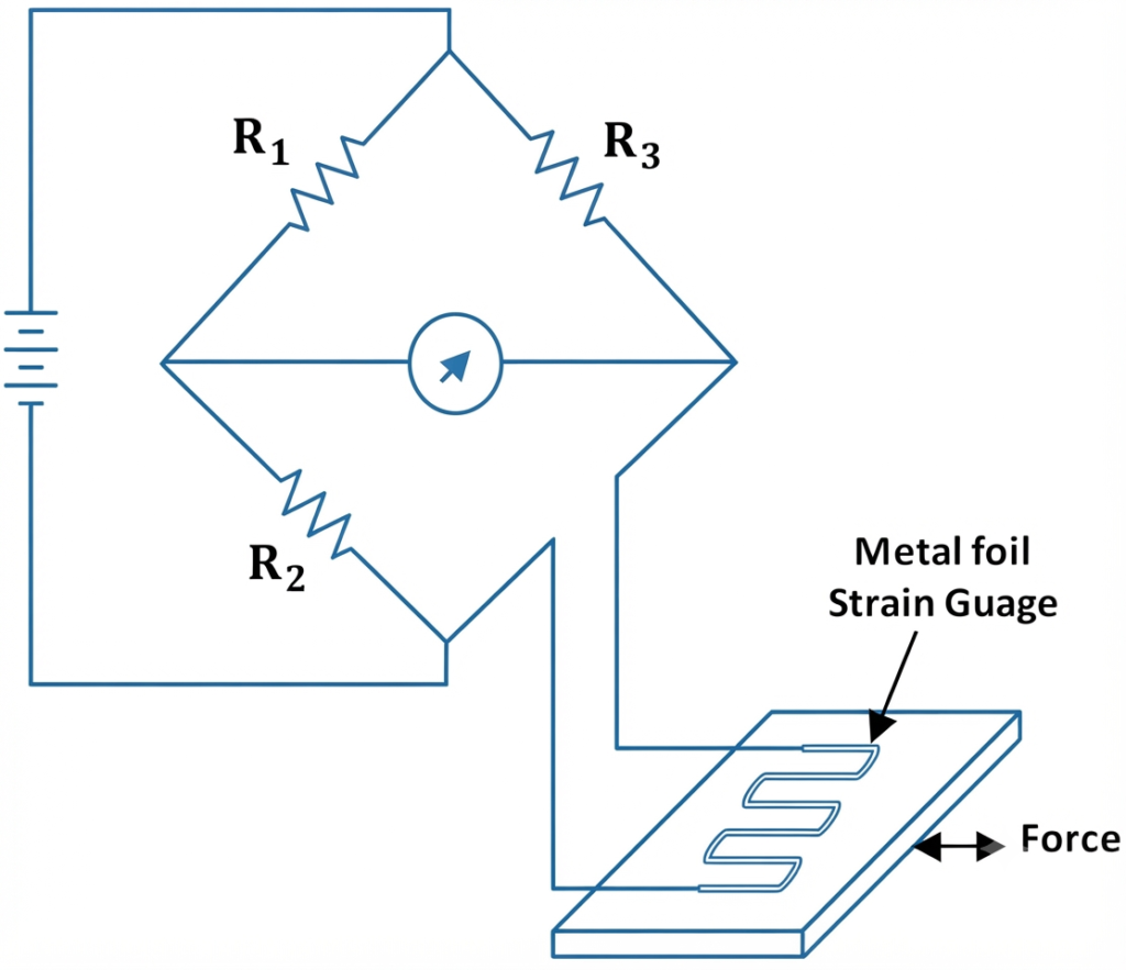
The operation of a bonded strain gauge involves the following steps.
Step 1: Application of pressure or force
An external force, load, or pressure acts on the component to which the gauge is attached.
Step 2: Deformation of the component
The elastic sensing member deforms. For example, a pressure-sensitive diaphragm bends when the pressure difference across it changes.
Step 3: Strain transfer
Because the gauge is bonded to the surface, its sensing grid experiences approximately the same local surface strain along the gauge’s measurement axis.
Step 4: Resistance variation
The deformation changes the length, cross-sectional area, and possibly the resistivity of the sensing element. Its electrical resistance therefore changes.
Step 5: Electrical signal generation
The gauge is connected to a Wheatstone bridge. The resistance change unbalances the bridge and produces a differential output voltage.
Step 6: Signal processing
An amplifier and signal-conditioning circuit process the bridge output. After suitable calibration, the instrument displays the corresponding strain, force, or pressure.
Bonded strain gauge in a pressure transducer
In a bonded strain gauge pressure transducer, pressure acts on a diaphragm or another elastic sensing structure. The resulting deformation produces tensile and compressive strains at different locations on the sensing element.
Multiple gauges may be mounted at selected positions and connected in a bridge circuit. Their arrangement determines how the desired strain components contribute to the output.
For example, a suitably designed diaphragm sensor can use several gauges to increase sensitivity and compensate for certain temperature effects.
The exact number, orientation, and location of gauges depend on the transducer design. Four-gauge arrangements are common in many pressure and force sensors, but they are not a requirement for every bonded strain gauge.
Advantages of bonded strain gauges
- Compact construction suitable for many industrial sensors.
- Direct strain transfer from the component to the sensing element.
- Good measurement performance when properly installed and calibrated.
- Compatibility with quarter-bridge, half-bridge, and full-bridge circuits.
- Availability in different grid geometries, resistance values, and temperature-compensation options.
- Suitable for measuring static and dynamic strain within the limits of the complete measurement system.
Limitations of bonded strain gauges
- Require careful surface preparation and bonding.
- Adhesive performance can limit operation at high temperatures or in harsh environments.
- Moisture, chemicals, and mechanical damage can affect long-term reliability.
- Installation errors can reduce strain transfer and measurement accuracy.
- The gauge and its mounting arrangement must be selected for the expected strain range and operating conditions.
Specifications of a Bonded Strain Gauge
The typical specifications of a bonded strain gauge include its physical dimensions, electrical resistance, excitation voltage, and sensing material.
| Parameter | Typical specification |
| Size | Approximately 3 mm × 3 mm × 3 mm; some designs may have dimensions around 2.5 mm × 12.5 mm |
| Electrical resistance | 120 Ω to 1000 Ω |
| Maximum excitation voltage | 5 V to 10 V |
| Construction material | Nichrome-copper alloys, nickel-chromium alloys, or nickel-iron alloys |
Note: These specifications are indicative. Actual dimensions, resistance values, and permissible excitation voltage depend on the strain gauge model and manufacturer.
Applications of bonded strain gauges
Bonded strain gauges are used in:
- Industrial pressure transmitters and pressure transducers.
- Load cells and electronic weighing systems.
- Torque measurement devices.
- Structural testing of bridges and buildings.
- Mechanical stress and fatigue analysis.
- Force measurement and materials testing.
- Automotive and aerospace component testing.
What Is an Unbonded Strain Gauge?
An unbonded strain gauge is a resistance strain sensor in which fine sensing wires are stretched between stationary and movable supports rather than bonded directly to the surface of the component being measured.
The wires are commonly arranged around insulating posts attached to the supporting structure. Relative movement between the supports changes the strain in the wires, producing a corresponding change in electrical resistance.
Unbonded strain gauges have been used in force and displacement transducers and in certain pressure-measurement systems.
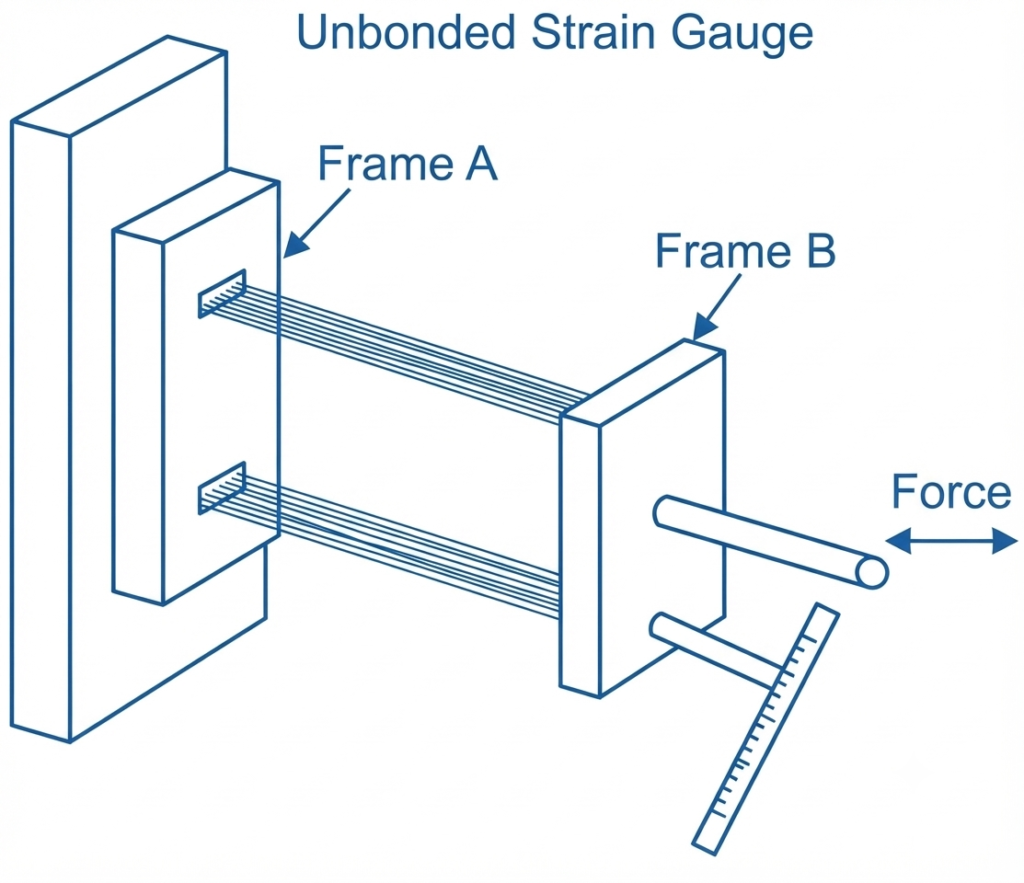
Construction of an unbonded strain gauge
A typical unbonded strain gauge consists of the following components:
- Fixed support: Holds one end of the sensing-wire arrangement in position.
- Movable support: Displaces in response to the applied force or pressure.
- Fine resistance wires: Form the sensing elements and respond to changes in length and tension.
- Insulating posts: Support and separate the wires electrically.
- Electrical connections: Connect the sensing elements to a bridge circuit.
- Mechanical frame: Maintains the arrangement and provides the required mechanical support.
The movable support may be connected to a diaphragm, spring, or other mechanical element. When that element moves, the sensing wires experience changes in tension.
Unlike a bonded strain gauge, the resistance wires do not need to be adhesively attached to the surface of the component whose movement is being measured.
Working principle of an unbonded strain gauge
The unbonded strain gauge operates by converting relative mechanical movement into a change in the resistance of fine wires.
Step 1: Application of force or pressure
The external quantity acts on the mechanical sensing element, such as a diaphragm or spring.
Step 2: Movement of the support
The sensing element moves slightly, causing displacement of the movable support relative to the fixed support.
Step 3: Wire deformation
The relative movement stretches some resistance wires and relaxes or compresses others, depending on the arrangement.
Step 4: Resistance change
The resistance of each wire changes as its dimensions and mechanical strain change.
Step 5: Wheatstone bridge operation
The wires are connected in a bridge arrangement. Their resistance changes produce a differential output voltage.
Step 6: Measurement and calibration
The output is processed by suitable electronics and converted into a calibrated measurement of displacement, force, or pressure.
Four-wire arrangement in an unbonded strain gauge
A common unbonded strain gauge arrangement uses four resistance wires connected as the four arms of a Wheatstone bridge.
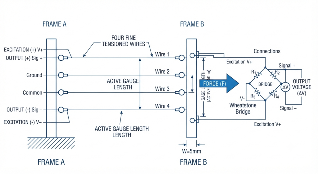
The wires are positioned so that movement causes two elements to experience increased tensile strain while the other two experience reduced tension or an appropriate opposing strain response.
The bridge connection is selected so that the resistance changes reinforce the desired output. This can improve sensitivity and help compensate for certain common effects, depending on the design.
The precise behaviour depends on the wire routing, support geometry, and electrical connections. Not every unbonded strain gauge uses exactly the same four-wire arrangement.
Advantages of unbonded strain gauges
- The sensing wires do not require direct adhesive bonding to the measured component.
- The mechanical arrangement can be designed to provide controlled wire tension.
- Multiple sensing wires can be incorporated into a bridge circuit.
- Suitable designs can offer good measurement stability.
- Mechanical travel stops or overtravel protection can be incorporated into some transducers.
- Can be used in specialised force, displacement, and pressure-measurement instruments.
Limitations of unbonded strain gauges
- Require a supporting frame and carefully arranged sensing wires.
- Mechanical alignment and wire tension influence performance.
- Moving parts and wire supports may increase construction complexity.
- Shock and vibration performance depends on the mechanical design and protection.
- Fine sensing wires can be damaged if the allowable mechanical travel or strain is exceeded.
- Calibration and temperature compensation are necessary for reliable measurements.
Specifications of an Unbonded Strain Gauge
The main specifications of an unbonded strain gauge include its wire dimensions, electrical resistance, excitation voltage, and sensing material.
| Parameter | Typical specification |
| Wire diameter | Approximately 0.003 mm |
| Wire length | Approximately 25 mm |
| Electrical resistance | 120 Ω, 350 Ω to 1000 Ω |
| Maximum excitation voltage | Approximately 5–10 V |
| Sensing materials | Nichrome, Constantan, and nickel |
Note: These values are typical figures from the provided specifications. Actual wire dimensions, resistance, and allowable excitation voltage depend on the particular strain gauge design and manufacturer.
Applications of unbonded strain gauges
Unbonded strain gauges may be used in:
- Selected pressure transducers.
- Force and displacement measurement systems.
- Mechanical measurement instruments.
- Specialised industrial instrumentation.
- Laboratory measurement equipment.
- Transducers in which relative movement between supports can be converted into resistance variation.
Their suitability depends on the required measurement range, mechanical construction, environmental conditions, and available transducer design.
Difference Between Bonded and Unbonded Strain Gauges
The main difference between bonded and unbonded strain gauges is how their sensing elements experience deformation. A bonded gauge follows the strain of the surface to which it is attached, whereas an unbonded gauge detects relative movement through changes in the strain of wires supported between fixed and movable parts.
The following table compares their major characteristics.
| Comparison factor | Bonded strain gauge | Unbonded strain gauge |
| Construction | Sensing grid attached to a component or elastic member | Fine resistance wires supported between fixed and movable parts |
| Sensing element | Commonly metallic foil or wire | Commonly fine resistance wires |
| Strain transfer | Through an adhesive or bonding layer | Through relative movement of the supports |
| Mechanical arrangement | Can have no moving parts in the gauge assembly itself | Generally includes a mechanical support arrangement with relative movement |
| Installation | Requires surface preparation and bonding when surface-mounted | Requires correct assembly and alignment of the supports and wires |
| Resistance variation | Produced by deformation of the bonded sensing grid | Produced by changes in wire strain as supports move |
| Bridge circuit | Can use quarter-, half-, or full-bridge configurations | Often uses multiple wires arranged in a bridge circuit |
| Shock and vibration | Can perform well with suitable mounting and protection | Depends on the frame, wire support, damping, and mechanical protection |
| Overtravel protection | Depends on the mechanical sensor design | Can be incorporated into the support mechanism |
| Temperature effects | Influenced by gauge resistance, specimen expansion, adhesive, and wiring | Influenced by wire resistance, support geometry, and surrounding temperature |
| Size | Can be very compact | Requires space for the wire-support arrangement |
| Typical uses | Load cells, pressure sensors, torque sensors, structural testing | Selected force, displacement, and pressure transducers |
| Maintenance considerations | Bonding condition and protective coating are important | Wire condition, support alignment, and mechanical movement are important |
Neither type is automatically more accurate, less expensive, or more durable in every application. These characteristics depend on the specific sensor design, manufacturing quality, operating environment, and calibration.
Bonded vs. Unbonded Strain Gauges: Which Is Better?
The choice depends on the measurement system and its operating requirements.
When should you choose a bonded strain gauge?
A bonded strain gauge is generally a practical choice when the sensing element must measure surface strain directly on a component or diaphragm.
Consider a bonded gauge when:
- The application requires compact sensor construction.
- The component’s surface strain is the quantity of interest.
- The mounting surface can be prepared properly.
- The adhesive and gauge can withstand the operating temperature and environment.
- The system needs to measure strain in a load cell, pressure transducer, or structural component.
When should you choose an unbonded strain gauge?
An unbonded strain gauge may be suitable when a transducer can use relative movement between mechanical supports to strain the sensing wires.
Consider an unbonded gauge when:
- The transducer design provides fixed and movable supports.
- The sensing wires can be maintained at the required tension.
- A controlled mechanical arrangement is preferred over direct surface bonding.
- The instrument can accommodate the required frame and mechanical protection.
- The application suits the available measurement range and transducer design.
The decision should be based on the complete sensor’s specifications rather than the gauge classification alone.
Role of the Wheatstone Bridge in Both Types
Both bonded and unbonded resistance strain gauges commonly use a Wheatstone bridge to detect small resistance changes.
A bridge contains four resistance arms. When the bridge is balanced, the differential output is ideally zero. When the sensing element’s resistance changes, the balance is disturbed and a voltage appears at the output.
For a conventional quarter-bridge arrangement with one active gauge and a small resistance change:
Where:
- = differential bridge output voltage.
- = bridge excitation voltage.
- = resistance change.
- = initial gauge resistance.
An instrumentation amplifier can increase the output signal for further processing.
The bridge configuration, gauge factor, excitation voltage, wiring, and calibration all affect the final measurement. Temperature compensation may also be required because resistance can change with temperature even when the intended mechanical load remains constant.
Conclusion
Bonded and unbonded strain gauges both measure mechanical deformation by detecting changes in electrical resistance, but their sensing arrangements differ.
A bonded strain gauge is attached to a component or diaphragm and follows its surface strain. It is widely used in load cells, pressure transducers, torque sensors, and structural testing.
An unbonded strain gauge uses fine resistance wires supported between fixed and movable parts. Relative movement changes the wire strain and resistance, making the arrangement suitable for selected mechanical and industrial transducers.
For reliable measurement, consider the construction, strain range, temperature effects, mechanical protection, bridge configuration, and calibration requirements. Selecting the correct arrangement helps achieve accurate and stable measurements in pressure instrumentation and other industrial applications.
Read Next:
- Transmitter: Types, Working Principle, and Examples
- SMART Transmitter: Working Principle, Components, Advantages
- Level Transmitter Calibration Procedure
- Level Transmitter: Types, Working Principle & Applications
- Differential Pressure Transmitter: Working Principle, Types
- Capacitance Differential Pressure Transmitter: Working Principle, Construction
- Piezoresistive Differential Pressure Transmitter: Working Principle, Diagram, Components, and Applications
- Strain-Gauge Differential Pressure Transmitter: Working Principle, Diagram, Components, and Applications
- Strain Gauge: Working Principle, Diagram, Types, and Applications
- Types of Strain Gauges: Working, Characteristics, and Applications